Voltage drop is super important when it comes to most projects, and I’m here to walk you through a single phase voltage drop calculation.
There are three main ways to calculate voltage drop, each with its own level of accuracy:
- Approximate
- Estimated
- Exact
I’ll be your guide through each method, and by the end, you’ll be a voltage drop calculation whiz and be able to choose the best method for your specific problem.
What is voltage drop?
Voltage drop is the decrease in voltage that happens as current moves through an electrical circuit. Think of it like losing water pressure in a hose because of a kink. This voltage loss occurs due to something called impedance.
Impedance is a circuit’s resistance to electric current flow, kind of like trudging through thick mud. However, impedance is more complex because it’s a mix of both resistance and reactance.
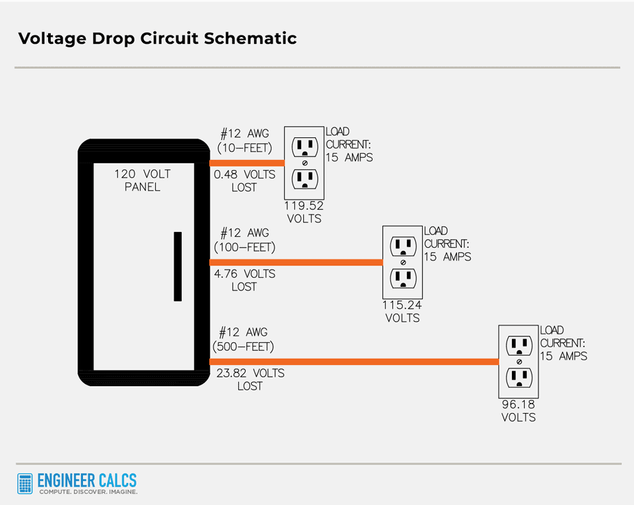
As a conductor carries current, the voltage drop is directly related to the conductor’s impedance and the current’s strength. The more current flowing, the bigger the voltage drop. Just like the longer the hose, the more water pressure you lose.
And the longer a conductor, the higher its impedance. That’s because all conductors have some level of impedance evenly spread along their length.
Voltage drop consequences in power systems
Voltage drop is like a leaky faucet in your power system, causing various issues. The drop happens when there’s a difference between the voltage at the source and the load.
One major issue is paying for electricity you don’t use, like ordering a large pizza but only eating half. When a utility company provides power, you pay for all of it, even if you don’t use it.
A bigger issue is that voltage drop can make your equipment operate at a lower voltage than intended. It’s like trying to run a marathon without enough fuel. Motors, for example, need a specific voltage to work properly. Low voltage can cause motors to draw more current, potentially leading to overheating.
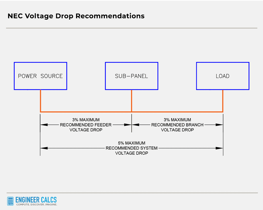
To tackle these issues, the National Electric Code (NEC) suggests that the maximum combined voltage drop for feeder and branch circuits shouldn’t exceed 5%. Also, the maximum voltage drop for either the feeder or branch circuit should not be more than 3%. Following these guidelines can boost power efficiency and improve your equipment’s life and performance.
For more info, take a peek at these crucial NEC sections on voltage drop:
- 210.19(A)
- 215.2(A)(4)
- 310.15(A)(1)
Also, check out the graphic below illustrating the NEC’s 3% and 5% recommendations.
Real-world voltage drop calculation example problem
Picture this: an empty 1-inch PVC conduit runs 550 feet, connecting a low-voltage power panel to a disused water well. The well once had a 1 HP pump, but now the client wants a new well 350 feet away and to upgrade to a 3 HP motor. This makes the total conduit run from the power panel to the new well 900 feet.
The motor’s specs are 3 HP, 240 volts, 1⌀, with a power factor of 0.90.
- Per NEC 430.151(A), the Locked Rotor Current (LRC) is 102 amps (for motor starting)
- Per NEC 430.148, the Full Load Amps (FLA) is 17 amps (for motor running)
Our mission is to determine the conduit size and conductor ratings feeding this new motor. Because of the long circuit run, we also need to calculate the voltage drop. This will help us figure out if we can reuse the existing 1-inch PVC conduit already installed, potentially saving a bunch of cash and headaches.
The theory behind single-phase, two-wire voltage drop
As we’re tackling a single-phase problem, it’s crucial to grasp how this affects our calculations.
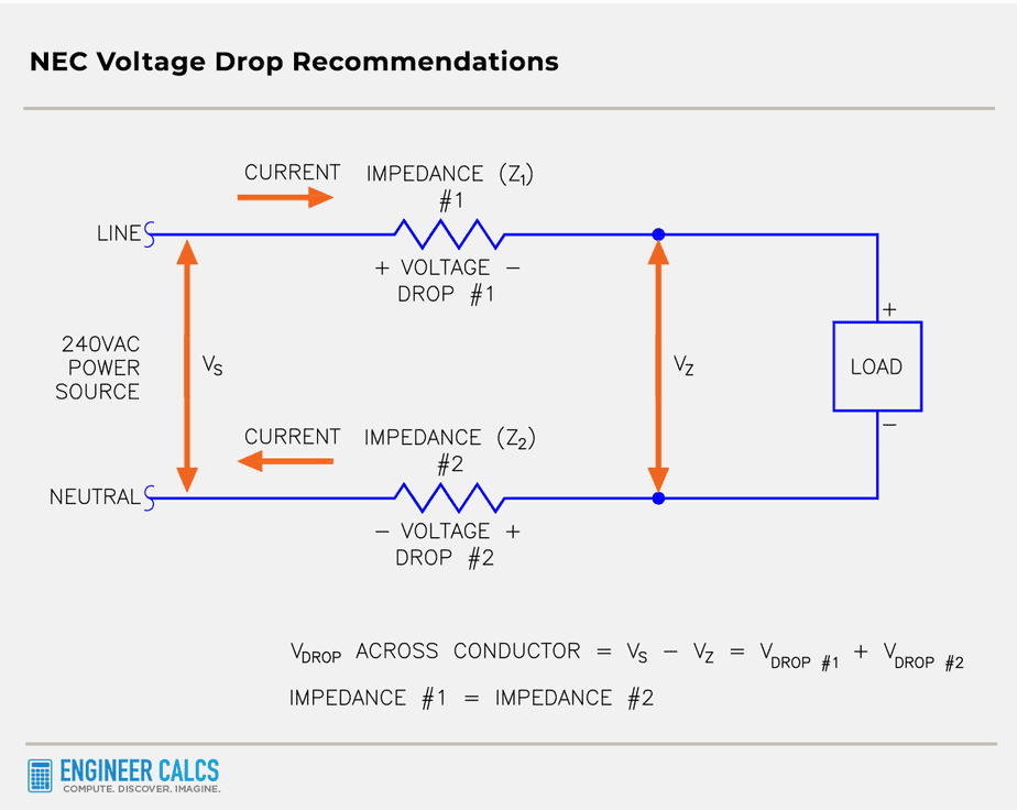
Check out the schematic below. I’ve used the resistor symbol to represent the conductor impedance, just to make things easier.
As shown, current flows from the power source to the load and then returns from the load to the power source. The impedance in both segments is equal, meaning the line current to the load is the same as the neutral current to the power source.
That’s why all the voltage drop equations are multiplied by two. The voltage drop is a round-trip calculated value in the circuit.

Important Note: In most cases, this scenario holds true. However, both the line and neutral wires need to be the same length and type to have equal impedances.
If the current returns through a different path, the voltage drop will differ on the return path. In these cases, we’d need to calculate the voltage drop separately for each wire. We can’t just multiply by 2 in these situations.
Voltage drop calculation assumptions
Before we dive into the nuts and bolts of the calculations, let’s look at the assumptions we’re making:
- Conductor temperatures are between 30°C and 40°C
- Termination temperatures are 75°C
- The load is balanced, so there’s no neutral current
- All power factors are lagging
- All conductors are stranded
These assumptions set the stage for our single-phase voltage drop calculation. They ensure we have a clear understanding of the context in which we’re working, and that our calculations are spot-on.
Approximate voltage drop calculation method for motor starting
Imagine we’re dealing with fire pumps. NEC 695.7 tells us that the voltage at a fire pump’s line terminals shouldn’t drop more than 15% of the rated voltage when the motor starts. This is crucial because a motor’s torque output is directly linked to its voltage, with torque scaling as the square of the voltage.
Suppose a motor has a nominal locked rotor torque of 100-foot pounds at 240V. If the voltage dips, the motor might only churn out 50-foot pounds of torque. If that’s less than the starting torque, the motor won’t even start!
Although our pump isn’t a fire pump, the 15% check still helps us ensure efficient power consumption with long conductor runs. It’s a solid rule of thumb to follow. For extra precision, you can check out the motor’s torque-speed curve.
So, the total voltage drop allowed in our circuit is 240 volts x 0.15 = 36 volts, which means the voltage at the load end of our circuit can’t be less than 204 volts.
Now, let’s figure out the wire size!
cmil = 
Where,
K constant = ohms-cmil per foot (copper has a K value of 12.9 ohms-cmil/ft)
I = current (or amperes) going to the load and returning from the load
L = length of conductor in feet (one-way)
cmil = circular mil area of the conductor (using Table 8 of Chapter 9 from the NEC)
cmil =  = 65,790 cmils
To calculate the voltage drop, we rearrange the equation.
 = 35.69 volts
 = 14.87% voltage drop
Looking at the NEC Table 8 of Chapter 9, a #2 conductor has a cross-sectional area of 66,360 cmils. This is greater than the calculated 65,790 cmils. So, a #2 conductor is a solid choice for now.
Approximate voltage drop calculation method for motor running
We start by calculating the total voltage drop allowed in the branch circuit, where 240 volts x 0.03 = 7.2 volts. The voltage at the load end of the circuit must be no less than 232.8 volts.
Now, let’s calculate the conductor size.
cmil =
Where,
K constant = 12.9 ohms-cmil per foot
Current (I) = 17 amps
Length (L) = 900 feet
Important Note: K is a constant value that stands for the electrical resistivity of the conductor material you’re working with. Different materials have different K values, which are fixed and don’t change.
To calculate K, you just multiply the electrical resistance of the material by its cross-sectional area, and then divide that by its longitudinal length. For copper, the K constant is 12.9 ohms-cmil per foot.
Now, about cross-sectional area, cmil (or circular mil) is a unit of measurement for sizing up circular objects – like wires, for example. To calculate cmil, you multiply the wire’s diameter (in decimal inches) by 1000, and then square the result. And guess what? NEC Table 8 of Chapter 9 has a nifty table of cmil values for us to use.
Time to crunch some numbers in our equation.
cmil =  = 54,825 cmils
According to NEC Table 8 of Chapter 9, a #2 conductor has a cross-sectional area of 66,360 cmils, which is more than our calculated 54,825 cmils. Meanwhile, a #3 conductor has a cross-sectional area of 52,620 cmils.
To find the voltage drop, we rearrange the equation.
 = 5.95 volts
 = 2.48% voltage drop
So, using the approximate method, a #2 conductor will do the trick. It meets both the motor’s starting and running conditions.
Estimated voltage drop calculation method for motor running
Let’s dive into the nitty-gritty of voltage drop calculation using the estimated method. This approach is more precise than the approximate method we chatted about before.
You see, the approximate method has some flaws. For instance, the K constant—representing the average DC resistance of a certain material—may cause inaccurate AC voltage drop calculations. Plus, the approximation equation disregards a load’s power factor and simply applies the K constant to any power factor.
In other words, the actual AC characteristics of conductors are left out of the approximation method.
However, the estimated method saves the day by using the Effective Z at a 0.85 power factor. This step-up from the DC copper resistance value used in the approximate method gives us a more accurate calculation.
Important Note: The Effective Z of 0.85 P.F. is usually a conservative estimate. For big conductors, it almost always results in the worst-case value. In my experience, this value tends to be on the safe side for most applications.
Here’s the equation we’ll use:  = 2 x I x Z x L
According to NEC Table 9 of Chapter 9, a power factor of 0.85 gives an impedance of 0.19 ohms per 1000 feet for the #2 conductor in PVC.
= 2 x 17 x 0.19 x  = 5.81 volts
 = 2.42% voltage drop
Exact voltage drop calculation method for motor running and starting
Alright, let’s dive into our third and final calculation method! We’re going to figure out the exact voltage drop using this equation for motor running:
![V_{D} = 2 \times (V_{S} + IRLcos(\theta) + IXLsin(\theta) - \surd[V_{S}^{2} - (IXLcos(\theta) - IRLsin(\theta))^{2}])](https://engineercalcs.com/wp-content/ql-cache/quicklatex.com-4d4d600fb0d0c029cbb50e02ea845fc5_l3.png "Rendered by QuickLaTeX.com")
In this case, I’ll use the resistance (R) and reactance (X) of the #2 conductor in PVC.
Where,
 (Voltage Source) = 120 volts
Current (I) = 17 amps
Resistance (R) = 0.19 ohms/1000-feet (from NEC Table 8 of Chapter 9)
Reactance (X) = 0.045 ohms/1000-feet (from NEC Table 8 of Chapter 9)
Length (L) = 900 feet
Running Power Factor = 0.90 or  = 25.8\degree
Now let’s plug our numbers into the equation.
![V_{D} = 2 \times (240 + (17)(0.19)(\dfrac{900}{1000})cos(25.8\degree) + (17)(0.045)(\dfrac{900}{1000})sin(25.8\degree) - \surd[240^{2} - ((17)(0.045)(\dfrac{900}{1000})cos(25.8\degree) - (17)(0.19)(\dfrac{900}{1000})sin(25.8\degree))^{2}])](https://engineercalcs.com/wp-content/ql-cache/quicklatex.com-026391d634933523dc8a8e5b8a7daca5_l3.png "Rendered by QuickLaTeX.com")
= 2 x (240 + 2.62 + 0.30 – 240) = 5.84 volts
 = 2.43% voltage drop
So, all three methods gave us pretty similar voltage drops!
Important Note: Smaller wire sizes have a lot more resistance than reactance, while larger conductors have more reactance than resistance. So, when working with big conductors, don’t forget to factor in power factors for voltage drop calculations.
Also, keep in mind that the power factor is different for motor starting and running. The power factor for starting is usually much lower, around 0.2 for modern motors. Plus, when you’re calculating for motor starting, use the motor’s Locked Rotor Amps (LRA) instead of Full Load Amps (FLA).
Remember, the power factor and current draw are closely connected for a given motor. When the power factor drops, the motor draws more current.
Exact voltage drop calculation method for motor starting
To wrap this up, let’s do one last calculation for motor starting using the exact method.
We’ll use a power factor of 0.20 with an LRC of 102 amps.
![V_{D} = 2 \times (240 + (102)(0.19)(\dfrac{900}{1000})cos(78.5\degree) + (102)(0.045)(\dfrac{900}{1000})sin(78.5\degree) - \surd[240^{2} - ((102)(0.045)(\dfrac{900}{1000})cos(78.5\degree) - (102)(0.19)(\dfrac{900}{1000})sin(78.5\degree))^{2}])](https://engineercalcs.com/wp-content/ql-cache/quicklatex.com-6ad26f93aba7a6e9a257a3c406109ffb_l3.png "Rendered by QuickLaTeX.com")
= 2 x (240 + 3.48 + 4.05 – 239.4) = 16.26 volts
 = 6.78% voltage drop
The voltage drop here is different from the approximate method’s output. That’s because we’re using a legit power factor value with the exact method.
Conduit fill calculation
After going through all the motor running calculations, we’ve figured out that a #2 conductor is the perfect choice.
Our conduit fill is (3) #2 Cu. THHN/THWN & (1) #6 Cu. Ground.
Here are the cross-sectional areas of our conductors:
- #2 THHN/THWN: 0.1158 in² (from NEC Table 5 of Chapter 9)
- #6 Cu.: 0.027 in² (from NEC Table 8 of Chapter 9)

According to NEC Table 4 Article 352 of Chapter 9, rigid PVC conduit schedule 40 has an allowable 40% fill of 0.581 in² for 1-1/4-inch conduit. Meanwhile, the allowable 40% fill for 1-inch conduit is 0.333 in².
So, for our new 350-foot conduit run, we’ll need to upgrade to 1-1/4-inch PVC conduit. Unfortunately, our existing 550-foot conduit is too small to reuse.
But hey, why not consider upsizing to 1-1/2-inch or even 2-inch conduit for such a long run? Sure, it might cost a bit more, but it’ll make pulling the conduit a breeze and save future headaches if the client decides to upgrade the pump again.
Single-phase voltage drop calculation wrap up
In our example, the client’s project site is growing, and they’ll need to upsize their existing 1-inch PVC conduit to at least 1-1/4-inch and pull (3) #2 Cu. THHN/THWN & (1) #6 Cu. ground conductors. It’s a costly addition, but crucial for keeping their system up and running smoothly.
When it comes to voltage drop calculations, the key is picking the right method. My two cents? Use the exact method when you have all the data you need. It offers more accurate results than the approximate method, helping you avoid expensive mistakes.
But keep in mind, be ready to defend your choice of voltage drop calculation method.
What do you think about the single-phase voltage drop calculation? Which single-phase voltage drop calculation method do you usually use?
So for a 3-wire 120/240V single-phase feeder to a remote service panel how is the voltage drop calculated say for a parallel run of conductors? I have a 700′ run from source to load and not exactly sure how to calculate it……just use kcmil for total conductor size and 2LIR/1000? The example via Table 9 does not address single phase condition…..second guessing myself now, lol!
High level, the voltage drop is basically half of the voltage drop for one conductor.