Cathodic protection is a great way to fight corrosion. I’ll go over a solar farm cathodic protection calculation to show you how it works.
We’re gonna figure out how many anodes we need for each stanchion, which will hold up the solar panels.
But first, let’s dive into the nitty-gritty of cathodic protection, so you get a better feel for the math we’re gonna do.
What is cathodic protection?
It’s a technique we use to keep metal surfaces from corroding. The idea is to turn the metal you want to protect into a cathode.
By making the metal a cathode, you keep it from oxidizing, since oxidation only happens to an anode.
And just so you know, rust is what you get when metal corrodes. This can happen when the metal’s exposed to any of the following:
- Water
- Damp air
- Wet soil or even wet concrete

Important Note: Metal deterioration comes from electron transfer, which is called corrosion. There are two types of corrosion processes: oxidation and reduction.
Oxidation is when a metal atom loses electrons in a chemical reaction with oxygen, forming a metal oxide. Reduction, on the other hand, is when a metal transfers electrons to some other material.
Let’s define a cathode and an anode:
- Anode (the active site): the metal that loses electrons during a chemical reaction
- Cathode (the less active site): the metal, liquid, or gas that gains electrons during a chemical reaction
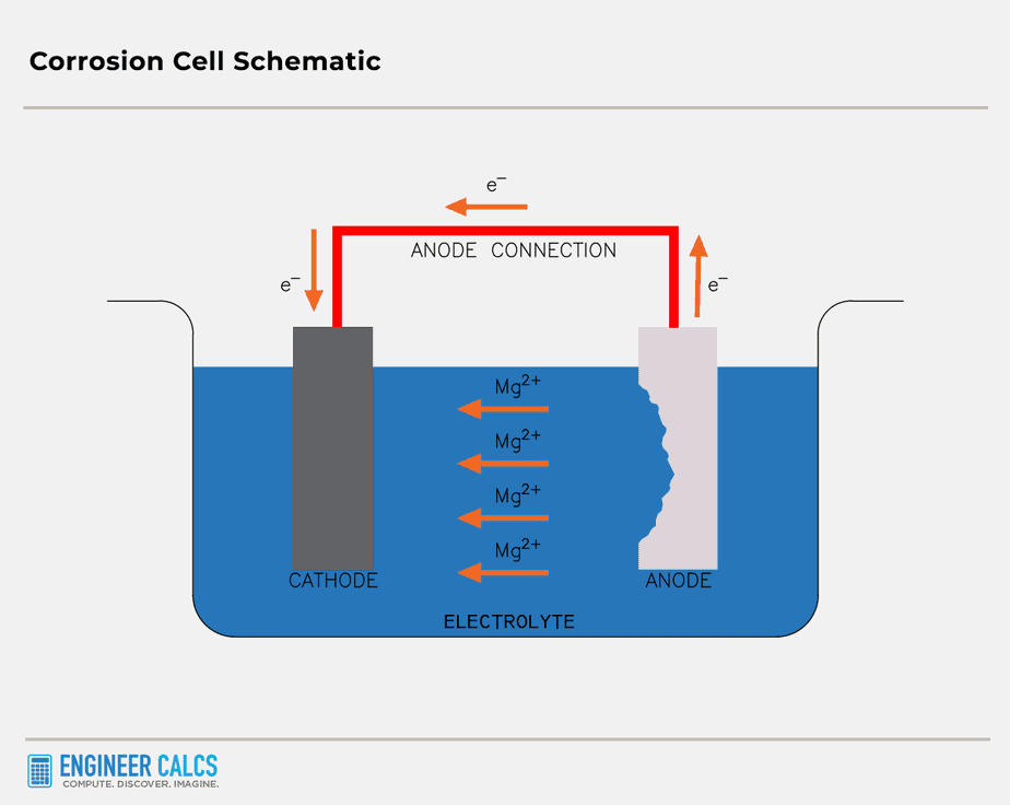
Now, for corrosion to kick in, you need three things:
- Two different types of metal, like steel and aluminum
- A medium (electrolyte) such as seawater or Earth, which lets ions flow and transport electric charges
- An electrical connection between the cathode and anode, allowing current to flow between the metals
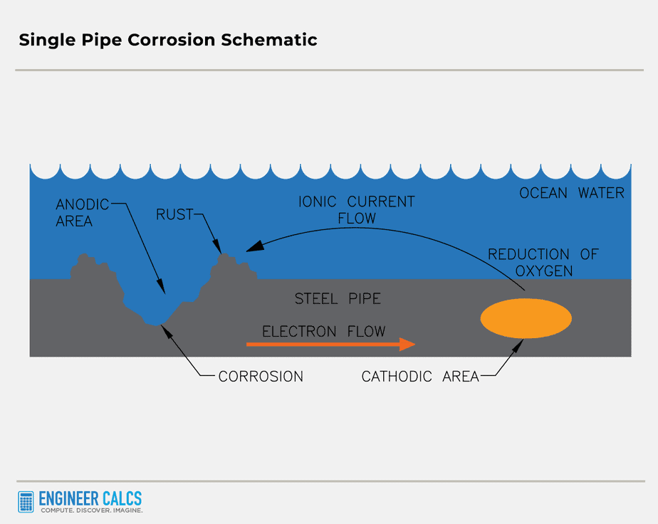
Important Note: The two different metals can be separate metals, or a single piece of metal with variations on the surface. These differences can be large, leading to non-uniformity on the metal surface. For example, a single pipe can have both an anode part and a cathode part.
Picture a pipe half-dipped in water with low oxygen concentration. The dipped half turns into the anode, while the other half with high oxygen concentration becomes the cathode.
How does cathodic protection prevent corrosion?
Cathodic protection is a nifty technique that stops corrosion by turning all the active (anodic) spots on a metal surface into passive (cathodic) ones. This is done by passing electrons to the metal in need of protection, like a massive steel pipe or a ship’s hull.
There are two main cathodic protection methods, each with its own perks and drawbacks in real-life situations:
Method #1: Sacrificial anode
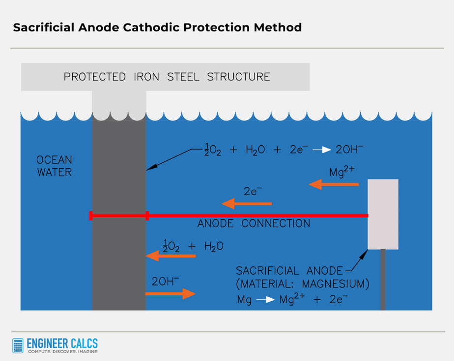
A sacrificial anode is a metal that is more reactive than the metal it is protecting. A more reactive metal loses electrons more easily, forming ions. For instance, when protecting iron, you would use a metal that is more reactive than iron, such as zinc or magnesium.
The sacrificial anode, also known as the galvanic anode, sacrifices itself to protect another metal from corrosion. It oxidizes in the electrolyte (soil or ocean, for example), generating electrons. These electrons flow to the metal being protected, forcing it to become a cathode. Moreover, the incoming electrons help restore the protected metal by reducing any oxidized parts and returning them to their original state. The electrons cause ferrous ions to revert to solid iron.
Important Note: It’s super important that the sacrificial material oxidizes before the protected material does, or the cathodic protection won’t work.
Method #2: Impressed current protection
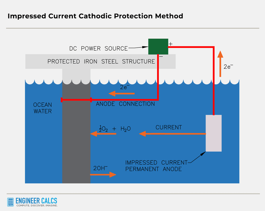
This method is pretty similar to the sacrificial anode technique, but with a twist: we use an external power source to create the electric current.
By pumping electrons onto the protected metal through an alternative power source, like a DC power supply, we make the metal a cathode, keeping it safe from oxidation.
The awesome part? You can use any electrically conductive material as an anode (iron, for instance, but not plastic). Plus, you won’t need to replace the anode, unlike in the sacrificial anode method where you have to swap it out when it corrodes.
Important Note: The key difference between these two methods is what gets oxidized. In the sacrificial anode system, the anode metal takes the hit, while in the impressed current system, water does the job.
Example of cathodic protection with a ship
Picture this: a massive ship cruising across the open ocean. It’s surrounded by a salty sea, which acts as an electrolyte solution. The mission? To protect the ship’s steel hull from the ravages of corrosion.
To achieve this, we lower a zinc anode into the water and electrically connect it to the hull. The zinc, being a reactive metal, oxidizes and pumps out electrons, turning the ship’s hull into a cathode.
Let’s say the hull is made of iron (Fe) and has already begun to oxidize. The electrons from the anode swoop in to save the day, reducing the Fe ions back to solid Fe atoms. This halts corrosion in its tracks, as only Fe bonds can cause corrosion.
Important Note: Zinc anode oxidation: 
If iron has oxidized on the ship’s hull, the following chemical reaction shows the Fe ions capturing the two electrons from zinc, giving us solid iron again, which is exactly what we want:
Reduction: 
Now, let’s say iron hasn’t rusted on the ship’s hull. Instead of transforming Fe ions back into solid Fe, we get a whole different reaction. We reduce water and oxygen into  , adding those extra electrons – ’cause they’ve gotta go somewhere, right?
Reduction: 
Your water heater and submarines
Fun fact: your water heater and submarines use cathodic protection too! Just replace your water heater’s sacrificial anode every few years, and it’ll last way longer. As for submarines, this ingenious technique lets these underwater behemoths stay submerged safely for extended periods.
In a nutshell, cathodic protection comes into play when the environment around a metal acts as an electrical conductor.
Cathodic protection calculation for a solar farm
So, picture this: we’re setting up a solar farm, and we’ve got 378 steel stanchions that need protection from corrosion. First things first, we need to figure out how much current (or electrons) should flow from each anode.
Here’s the equation we’ll use to calculate the current output needed to protect our embedded steel structures:

Where,
 : factor for uncoated steel is 150,000
f: anode factor is 1.90 for a 42lb long shape 3″ x 3″ x 72″ magnesium anode
Y: structure to soil potential correction factor for standard -0.85 volt differential is 1.0
 : soil resistivity in ohm-centimeters = 1951 ohm-centimeters for our location per test report
 : current output in milliamperes
Now, let’s crunch the numbers:
 = 146.08 milliamps output per anode
Since the soil at our solar farm is pretty corrosive, our stanchions need a current of 15 milliamperes/ of surface.
The total embedded surface area for all 378 stanchions is 1,669,920  or 11,597 .
So, (11,597 ) x (15 x  Amps/) = 173.95 Amps
I = 173.95 Amps (total current requirement) = 173,950 milliamps
Considering a 10-year life, we can calculate the total weight of anodes with this equation:

Where,
W: weight of anodes
 : projected life in years
I: total current required in milliamps
 = 40,633 pounds of magnesium anodes
Now let’s figure out how many anodes we need:
 = 967.5 anodes
To find the number of anodes per stanchion:
 = 2.56
We’ll round up to 3 anodes per stanchion = 3 x 378 = 1134 total anodes
 = 11.72 years anticipated life
Important Note: The anodes are 3-inch x 3-inch x 72-inches, installed in 6-inch diameter holes and 72-inches deep. They’re placed about 10 feet from the stanchion they’re protecting.
General rules of thumb with sacrificial anode system designs
Alright, let’s talk about the basics of sacrificial anode system designs. Remember Ohm’s Law? It’s like this:

Where,
I: current flow (in amps)
R: circuit resistance
V: voltage difference between the anode and cathode
In action, the current starts off high because of the huge voltage difference between the anode and cathode. But over time, this potential difference dips as more current zooms from the anode to the cathode. Eventually, the current dwindles with the polarization of the cathode.
As for circuit resistance, let’s go back to our ship example. The path through the saltwater, metal, and any linked cables make up the resistance.
Important Note: Here are some general rules of thumb for anodes:
- The length of an anode dictates the generated current, which in turn determines the metal area you can protect.
- The cross-sectional area of an anode, based on its weight, determines how long you can shield the metal.
Cathodic protection calculation wrap up
Without cathodic protection, our world would look totally different. We’re always installing metals in gnarly corrosive environments, like ships cruisin’ across the oceans.
It’s mind-blowing how much work goes into every installation, most of which can’t be seen with the naked eye.
So, what do you think about cathodic protection calculations? Which type of cathodic protection do you see getting installed most often?
Many Efforts to explain the crucial information
The soil resistivity will change with the weather (rainfall). Is the goal to keep a constant current as the resistivity changes, or a constant voltage (increasing the current when the soil gets wet)? How much total power is generally needed per square foot of buried metal?
Great questions!
Correct; the upper layer resistivity greatly varies with the season. Low temperature and low moisture both increase the soil resistivity.
There are many applications to consider – this isn’t a black and white question; generally speaking though, say the cathodic protection circuit resistance changes greatly at a field location due to a seasonal change (dry to wet) – the anode to earth resistance alters – an automatic rectifier, which is current controlled, would be used to maintain the correct applied current to the protected structure.
Now, if you have an above grade water tank, with varying water elevations inside, you’d typically find a potential controlled unit installed. This will allow you to maintain a fixed potential on a set reference cell in said tank, as the surface area requiring protection constantly changes with the fluctuating water level (i.e. the current requirement constantly changes).
To your last question, this is a highly subjective question. Too many variables at play.
Interesting. So the idea is to maintain a constant current per unit surface area. If the surface area is fixed, e.g. for a buried pipe, then the applied voltage needs to change dynamically as the soil resistivity changes to maintain the fixed current. If several variables are changing simultaneously, as in your tank example if the water level, temperature, and perhaps salinity or mineral content are all changing at once, then the system needs to be able to sense the water level to determine the surface area involved, then, like the first example, adjust the voltage to maintain a fixed current appropriate for the surface area involved at that moment.
In the case of something like a pipe network that is essentially infinite in size, does the pipe need to pass through electrical isolators periodically so the current and voltage can be kept manageable and safe for those living or working around the equipment?
I am trying to get a sense of the cost tradeoffs of cathodic protection versus material cost, which is why I needed a wattage figure. For your solar farm example, where the needed current is 174A, I would assume that it would take a lot of voltage to drive that much current through the soil so there are substantial ongoing operating costs for cathodic protection, which is hopefully justified by the lower up-front cost of using uncoated steel versus steel that is hot-dip-galvanized (HDG), plastic-coated, or stainless to block the galvanic corrosion process.
Sorry, missed your response – I never received a notification.
Your overview is correct – maintaining the current in the fashion you expounded over would be optimal when possible.
You can utilize one cathodic protection system for say a single relatively large facility if you properly calculate the current demand, and rectifier and anode sizes. But for a pipeline stretching miles, you’d probably need to utilize separate cathodic protection systems. The drive voltage would become compromised (i.e. voltage drop) as you alluded. Also, impressed current anodes are supplied with recommended current densities – higher current densities would reduce the anode’s life.
Overall though, there are many variables you need to consider, which a cathodic protection engineer would hopefully be able to detail/design. Then you need to do a cost-benefit analysis.