CT saturation calculations are critical for power system operations, as they reveal how well a CT can perform under non-ideal conditions.
I’ll walk you through the CT saturation calculation process, step by step. I’ll share all the nitty-gritty details you need to gather along the way.
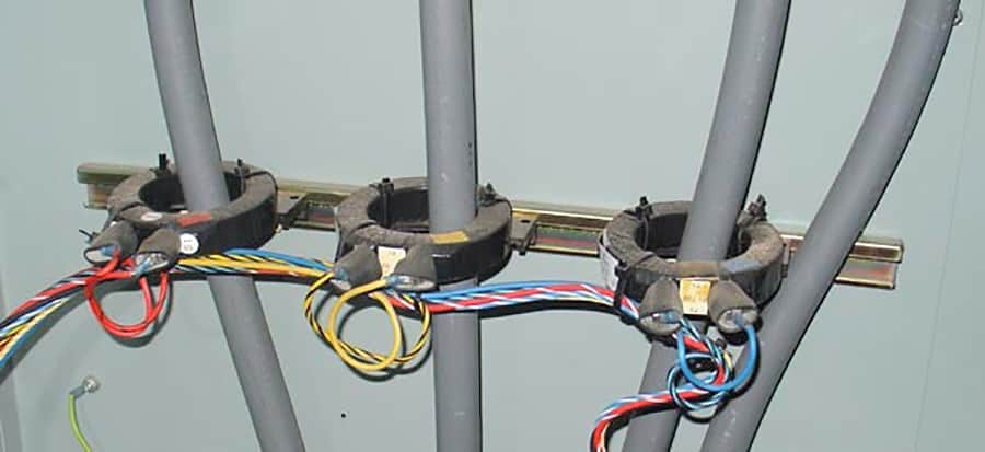
But before we dive into the weeds, let’s take a moment to appreciate CTs and their importance in power systems. Once you understand their value, you’ll be able to fully grasp the significance of this calculation.
What happens when a CT saturates?
The secondary current stops following the primary current proportionally. This means the secondary current can vary depending on the CT’s saturation level. For example, with a 100:5 rated CT, 200A passing through the primary winding would normally result in 10A on the secondary winding. However, with a saturated CT, you might only see 5A.
CT saturation can be caused by a variety of factors:
- High primary current from fault conditions
- Open circuit conditions on the CT’s secondary side
- The high burden on the CT’s secondary side
- Improper tapping down of a CT
- DC offset current
- High x/r ratio in a circuit
The knee point is where a CT saturates, and you can find it on a CT’s excitation curve. Remember, a CT’s accuracy class isn’t the knee point – it’s shown as a C rating.
For instance, a 10P20 C400 CT rating means the CT has to develop 400V across a 4-ohm burden at 20 times over current. So, that’s 20 x 5 Amps x 4 ohms = 400V, all without exceeding a 10% error (an excitation current below 10A).
According to IEEE C57.13, the knee point voltage is typically about 80% of the accuracy limiting voltage. For a CT rated C100, that’s about 80 volts. Keep this in mind when working with CTs.

Important Note: Saturated CTs can cause chaos for your electrical devices. Metering, measurement, and protective devices may read invalid values because the secondary current no longer matches the primary current.
But that’s not all. Incorrect CT settings can be downright hazardous. Without proper coordination, your electrical devices could blow up, causing extensive damage and putting people’s safety at risk.
Metering versus protection purpose CTs
For monitoring current and protecting your electrical devices, CTs are your go-to. But remember, not all CTs are created equal. Each one is uniquely designed for its specific use case.
Metering CTs are high-precision transformers that handle standard burdens and loads. They offer high accuracy when it comes to low to maximum current readings, making them perfect for utility companies.
Protection relaying CTs, on the other hand, are designed to work across a wide current range. While they’re less accurate than metering CTs, their main job is to detect high fault currents and protect your devices accordingly.
It’s worth noting that metering CTs can have larger errors during fault conditions, where currents can be several times greater than normal values for short periods. But that’s not a biggie since metering isn’t a concern during faults.
When calculating CT saturation, knowing which CT to use is vital. So, make sure you get to grips with the different CT applications to ensure your devices are properly protected and monitored.
Real-world substation CT saturation calculation
The CTs we’ll be using in our calculation are for substation relay protection.
To perform this calculation, we’ll use the following information:
- Maximum available fault current at 115,000 volts: 24,900 amps
- CT secondary wiring: #10 AWG copper with 1.3 ohms per 1000 feet resistance
- Wiring run from breaker CT to relay meter: up to 500 feet, making the total circuit length 2 x 500′ = 1,000′
Important Note: Picking the right CT accuracy class is key for accurate and reliable measurements, but it doesn’t have to be rocket science!
To nail it, consider the CT’s burden (the load it carries) and the fault current. This helps you figure out if you need a C100, C200, or C400 CT accuracy class.
The right accuracy class ensures a linear output from the CT, especially when responding to high fault currents. To choose the perfect accuracy class, you need to know the CT’s burden, which includes everything from the protective relay to CT wiring and any devices in between (like test switches and terminal blocks).
If you have long CT wiring, you’ll need a higher-class CT to deal with the increased resistance. Let’s assume the burden is fixed at 1 ohm for a C200 CT, and see what happens when the fault current goes from 100A to 400A:


So, we need a C400 rated CT for the 1 ohm burden.
A C400 CT calculates to, 
CT (1x, 3x, 5x) to existing 115,000 differential relay GE L90
CT = 2000:5A MRCT connected 2000:5A (400:1)
Important Note: Our fault current is 24,900 amps, so we need an accurate CT to handle it.
Let’s use a 10P20 CT with a 10% accuracy up to 20 times its primary rated current. With this, we can calculate the needed CT ratio: 24,900/20 = 1,245A. So, we need a CT ratio of 2000:5A.
Another way to look at it: a 2000/5 CT is 20 x 2,000 = 40,000 Amps. This means the CT will stay accurate in the field, even with a 24,900A fault.
Keep in mind, the burden significantly affects CT accuracy. The lower the burden on the CT secondary, the higher the saturation point for a given CT. For example, if a 10P20 50 VA CT has a 25 VA burden, it won’t saturate at 20 times the rated primary current, but at 40 times (50/25 x 20).
GE L90 relay burden = 0.2VA at 5 Amp input
0.2 VA/5A = 0.04 ohms
Important Note: Old electromechanical relays usually have high burdens, needing high CT accuracy classes. In contrast, modern microprocessor relays have much lower burdens.
CT Burden = CT lead resistance + relay burden
= (2) x (500′) x (1.3 ohms / 1000′) + 0.04 ohms
= 1.3 ohms + 0.04 ohms = 1.34 ohms
Secondary amps at maximum fault duty
To account for any errors, I’ll round the 24,900A fault current to 25,000A.
 = 62.5 Amps
= 62.5 x  = 83.8 volts
The minimum accuracy class of the CT should be C100.
Important Note: High voltage equipment in U.S. utilities typically needs C800 accuracy class CTs, like those for breakers and transformers in substations, no matter the available fault current.
But, it’s crucial to think about the physical space for installation in retrofit projects. C800 rated CTs might not fit in an existing enclosure due to their larger size. That’s why CT sizing is both a science and an art!
CT (1y, 3y, 5y) to existing 115,000 differential relay ABB 350
CT = 2000:5A MRCT connected 2000:5A (400:1)
ABB 350 relay burden = 0.45VA at 5 Amp input
0.45 VA/5A = 0.09 ohms
CT Burden = CT lead resistance + relay burden
= (2) x (500′) x (1.3 ohms / 1000′) + 0.9 ohms
= 1.3 ohms + 0.09 ohms = 1.39 ohms
Secondary amps at maximum fault duty
= 62.5 Amps
= 62.5 x  = 86.9 volts
The minimum accuracy class of the CT should be C100.
CT saturation calculation wrap up
CT saturation calculations may appear mundane, but they play a key role in ensuring your power system runs like a well-oiled machine. With spot-on calculations, you can rest assured that your metering and protection schemes will work reliably.
On the flip side, using the wrong CTs can lead to catastrophic power system failures, costing millions and putting lives at risk. That’s why getting your CT saturation calculations right is a big deal.
So, don’t underestimate these calculations. Take the time to count your CT loads and use the maximum fault current to size your CTs just right.
Do you have any CT saturation calculation tips? Do you find sizing CTs feels like an “art”?
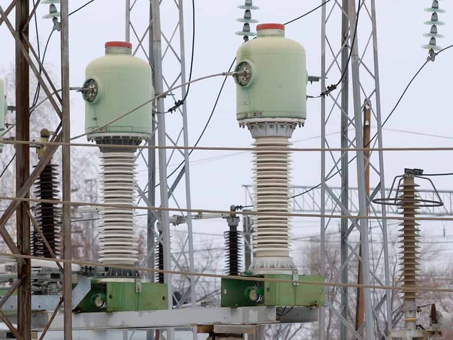
Featured Image Photo Credit: Vivan755 (image cropped)
I have found in textbooks that Ohmic value of burden is calculated by dividing the VA by square of the rated secondary current, whereas you have calculated the same by dividing VA by the rated secondary current instead of square of the secondary rated current.