Electromechanical relays are like the unsung heroes of our power grid, and they owe their superpowers to a few simple parts.
So, let’s dive right in and explore these parts to see how these incredible little devices work!
What is an electromagnet?
The term ‘electromagnet’ can be broken down like this:
- Electro: reminds you of electricity
- Magnet: yep, just like a regular magnet
So, an electromagnet is a magnet that needs electricity to work. The ‘mechanical’ part of the relay is all about the moving bits. In a moment, we’ll take a closer look at how everything comes together.
Important Note: When electricity flows through a wire, it creates a magnetic field. This field is a lot like what you’d find around a bar magnet. If you want to make that magnetic field stronger, just add a ferromagnetic material like iron into the mix. It’ll help concentrate the magnetic flux.
Ready to make your own electromagnet? Easy! Wrap a wire around a big steel nail, and connect both ends of the wire to a battery like in the illustration below.
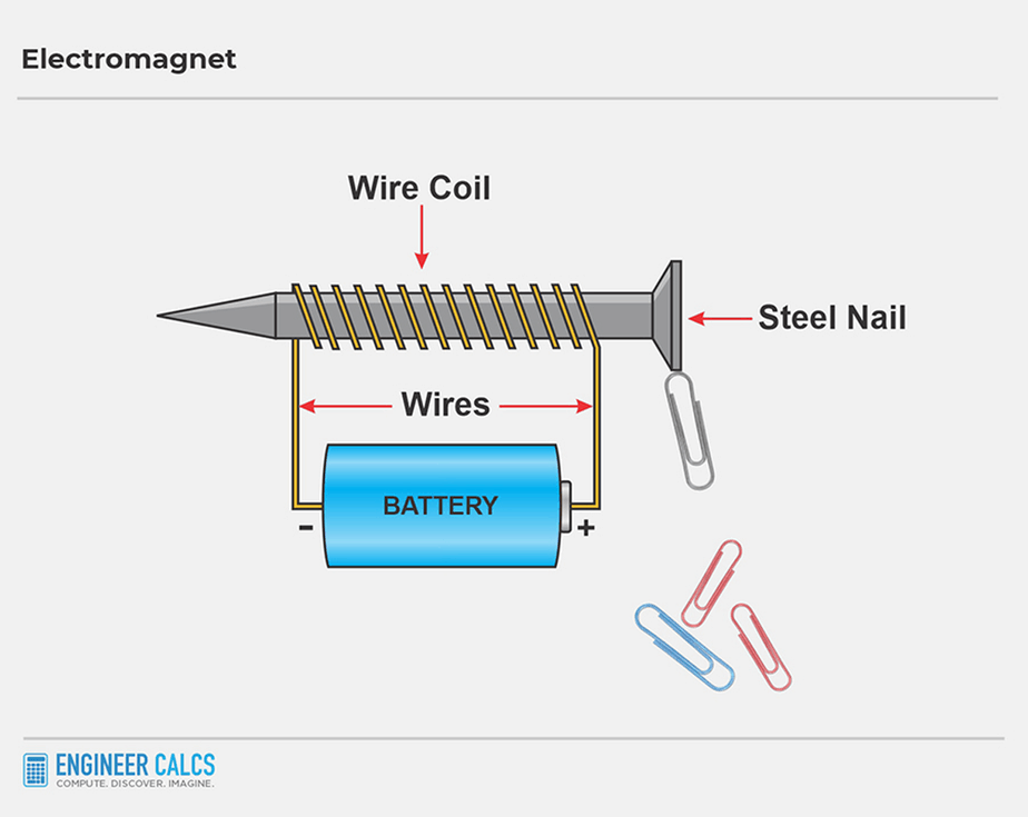
As the electric current flows from the battery through the wire coil, it magnetizes the steel nail. Your nail can now pick up paper clips. But once you disconnect the wire, the paper clips will fall. Give this experiment a whirl at home to get a real feel for the science behind it.
Important Note: The magnets sticking to your fridge are permanent magnets. Our DIY electromagnet, on the other hand, is the switch-on, switch-off type. It only gets magnetized when there’s electricity running through it.
Real-world application of electromagnets
Electromagnets are the beating heart of electromechanical relays. Nowadays, solid-state relays are becoming all the rage, using electronics to switch current paths. But I still see good ol’ electromechanical relays holding their own in industrial facilities.
Electromechanical relay operation
Now, let’s tie it all together by checking out Schematic #1:
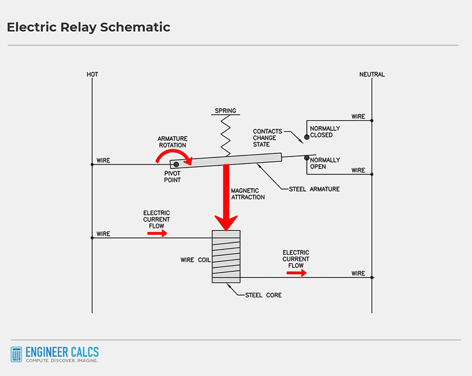
Schematic #1
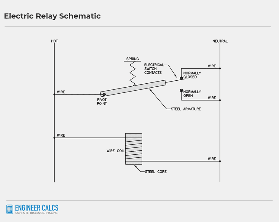
At the bottom rung, you’ll find a steel core, similar to our DIY steel nail wrapped in wire. When current runs through this core, it becomes magnetized.
On the top rung, there’s a steel armature featuring a pivot point on the left and electrical contacts on the right. Think of the armature like a lever with two positions:
- N.C. contact = Normally Closed contact
- N.O. contact = Normally Open contact
The steel armature is also hooked up to a spring. When the spring is relaxed, it holds the armature snug against the ‘normally closed’ contact. As current flows, it travels through the armature and N.C. contact.
There’s a tiny air gap between the N.C. and N.O. contacts too, stopping current from flowing through the N.O. contact from the armature when the spring is relaxed.
Important Note: When there’s no current flow, we say a relay is in a “normal state.” This is the industry lingo.
In Schematic #1, the steel armature connects to the N.C. contact in its normal state.
Electromechanical relay with electric current flow
So, let’s dive right back into the schematic we were talking about earlier! Now, we’ve got current flowing through that steel core. Picture those red arrows in Schematic #2, showing us which way the electricity is movin’.
Schematic #2
Here’s what happens step by step in Schematic #2:
- The current flows, turning the steel core into a magnet.
- The magnet attracts the armature, pulling it down toward itself.
- The spring attached to the armature stretches.
- The armature connects with the N.O. (normally open) contact.
A new electrical path forms, and the current travels through the N.O. contact. When the current stops flowing, the spring returns the armature to its original position, connecting with the N.C. (normally closed) contact.
Important Note: The purpose of a relay is to switch the current path in a circuit. It’s an electrically operated switch that makes electric circuits more flexible through circuit control.
Electromechanical relay operation for turning on lights
Let’s look at a real-world example of how an electromechanical relay powers two lights of different colors.
Schematic #3
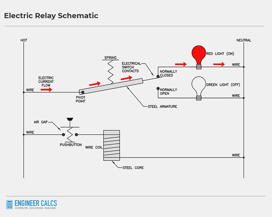
- The N.C. contact has a red light in series with it
- The N.O. contact has a green light in series with it
On the left of the second rung, there’s a push button. When pressed, the current flows through the steel core. When not pressed, an air gap forms, preventing current flow. As a result, the armature connects with the N.C. contact, turning on the red light. The red arrows show the current flow, traveling from the hot to the neutral wire.
Without any intervention, the red light stays on as shown in Schematic #3.
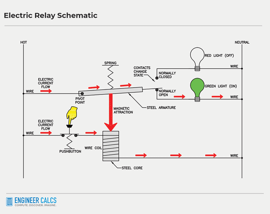
When you press the button, the air gap in the second rung closes. The current flows through the wire coil, magnetizing the steel core. The steel core then pulls the armature down, and the lights switch. You can see the new circuit in Schematic #4 below, with the green light on.
When you release the push button, the circuit returns to its normal state. The green light turns off, and the red light turns on again.
Schematic #4
Ladder diagrams with electromechanical relays
To make the previous diagrams easier to understand, let’s see what you would find on a real design drawing. The armature and steel core were physical representations to help explain the concept.
Below, we’ll convert the previous Schematic #5 into Schematic #6.
Schematic #5
Schematic #6
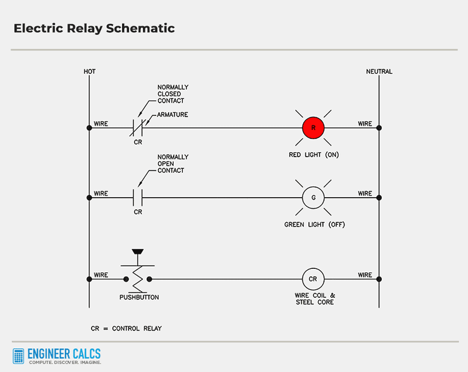
Zoomin’ in on Schematic #6, you’ll see two parallel lines on the top and middle rungs. Those are the electrical contacts.
- On the top rung: there’s a diagonal line cutting through the contact, which is the armature. When it’s actuated, it closes the air gap and creates a path for the electric current to flow, lighting up that red light!
- On the middle rung: the parallel lines are still separated, meaning the armature isn’t touching the N.O. contact in the relay’s normal state. So, no current flows, and the green light stays off.
Down on the third rung, you’ll find the wire wrapped around the steel core, which is the ‘CR’ circle. ‘CR’ stands for Control Relay. Notice how the contacts also have ‘CR’ labels, showing they’re associated with the ‘CR’ control relay.
The push button is just like before, and those last two symbols represent our trusty red and green lights on rungs #1 and #2.
Now, Schematic #6 works similarly to Schematic #3, which we already chatted about. The red light stays on unless you press that push button. When you do, CR charges up, the green light turns on, and the red light turns off. Check out Schematic #7 below to see it in action.
Schematic #7

How to read and follow electromechanical relay operations in schematics?
By industry standards, control relays are shown in their de-energized state on schematics. Let’s revisit Schematic #6.
When the CR is de-energized, the N.C. CR contact in the top rung is closed. Meanwhile, the CR contact in the middle rung stays open. So, electrical contacts can be either:
- Open
- Closed
Now, when CR gets energized (thanks to current flowing through it), just flip the state of the electrical contacts. The N.O. contact turns into a N.C. contact, and the N.C. contact becomes a N.O. contact.
Electromechanical relay operation wrap-up
Once you’ve mastered electromechanical relay operations, you can whip up some seriously cool designs. You can make machines dance to your tune, no computers needed.
And you know what? This amazing power ignited a whole wave of innovation. Power grids became ultra-efficient, and other industries started thriving.
Finally, I want to give a shout-out to Philip J. O’Keefe. His blog and support really helped me when I was a newbie engineer, and inspired this post.
What do you think about electromechanical relays? Have you ever created an electromagnet?
Author Bio: Koosha started Engineer Calcs in 2019 to help people better understand the engineering and construction industry, and to discuss various science and engineering-related topics to make people think. He has been working in the engineering and tech industry in California for well over 15 years now and is a licensed professional electrical engineer, and also has various entrepreneurial pursuits.
Koosha has an extensive background in the design and specification of electrical systems with areas of expertise including power generation, transmission, distribution, instrumentation and controls, and water distribution and pumping as well as alternative energy (wind, solar, geothermal, and storage).
Koosha is most interested in engineering innovations, the cosmos, sports, fitness, and our history and future.