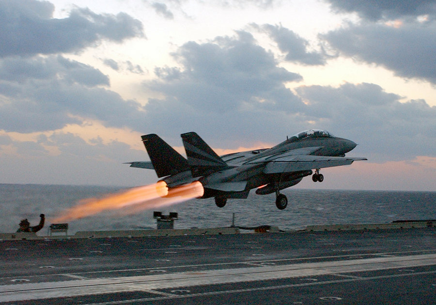
Let me walk you through the electrifying math behind an F-14 Tomcat Carrier Launch that adds to the allure of Tom Cruise’s Top Gun movie.
But first, let’s grasp the concept of aircraft carriers and their connection to jets.
The ocean’s airports
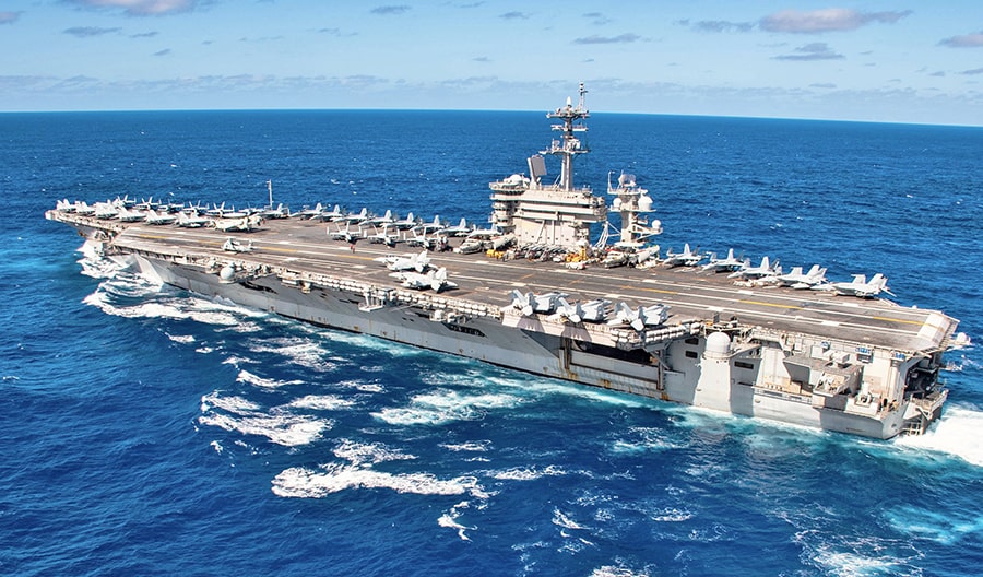
Picture this: a colossal airport floating in the ocean.
Meet the USS Theodore Roosevelt, a nuclear-powered aircraft carrier that towers 20 stories above the waves and stretches 1,092 feet long, boasting a massive 196,000 square-foot flight deck.
This mighty ship is home to over 80 airplanes and around 6,000 people for months on end. But how do fighter jets manage to take off from these behemoth floating airports? Well, that’s where things get interesting…
The science behind airplane takeoffs
According to Bernoulli’s principle, when fluids (in our case, air) move faster than their surroundings, they exert less pressure. Our goal is to create less pressure on top of the wings than below by going fast. This pressure difference generates an upward force, lifting the airplane.
But with a limited runway, planes on aircraft carriers rely on two unique features that you won’t find at land airports to gain speed.
#1 Catapult system
While a typical airport runway stretches 2,300 feet, an aircraft carrier’s runway is just about 300 feet long. That’s 2,000 fewer feet for planes to build up speed for takeoff.
Enter the steam-powered catapult. This incredible piece of machinery generates enough force to hurl planes from 0 to 170 miles per hour in a mere 2 seconds. However, the catapult force must be adjusted based on the airplane’s:
- Weight
- Aerodynamic shape
- Engine output
Get the catapult pressure wrong, and you could have a disaster on your hands:
- Pressure set too low: The plane plummets into the ocean, moving too slowly.
- Pressure set too high: The sudden jolt might snap the airplane’s nose gear.
#2 Ocean assistance
As aircraft carriers speed through the ocean, they can create additional airflow on the flight deck when moving in the same direction as a jet’s takeoff. This bonus airflow reduces the amount of thrust a jet needs.
Catapult system speed calculation
For each launch, operators tailor the catapult’s settings to the specific plane type, while also taking into account:
- Wind speed across the aircraft carrier deck
- Air density
- Airplane carrier speed

Important Note: Launching into the wind, the catapult needs to generate more force because the oncoming wind decreases a jet’s speed.
For our F-14 Tomcat carrier launch calculation, we’ll set aside these other variables and focus on the F-14 Tomcat, Maverick’s (Tom Cruise’s) fighter jet of choice. This awe-inspiring jet can sweep its wings backward and forward to achieve two goals:
- In flight for high speed, the wings swing back to create a sleek, aerodynamic shape.
- During takeoff and landing, the wings swing open to maximize the surface area of the wings (we’ll see why this is crucial later).
Important Note: The F-14’s wings look undeniably cool, but they were a maintenance nightmare. With countless moving parts, there were endless opportunities for failure. Plus, all that extra hardware bumped up the jet’s weight.
How fast does the catapult shuttle need to zip to launch an F-14 Tomcat into the skies?
The Aerospace Web says the max takeoff weight of an F-14 Tomcat is a whopping 74,350 pounds (33,725 kilograms). We’ll plug this weight into the lift formula to crunch the numbers.

Where,
 = lift force in pounds or newtons (equal to the F-14 Tomcat’s weight)
 = lift coefficient (i.e. the max takeoff lift coefficient)
 = air density in the takeoff region – at sea level, it’s is 0.0023769
 = true airspeed (i.e. how fast the airplane goes)
 = wing surface area (the F-14 Tomcat has a wing area of
  when fully forward)
Important Note: The value is usually found through experimentation. It takes into account the shape, inclinations, material density, and flow conditions of a wing. This value shows how well a plane can take off, depending on its airfoils and wings.
Using Haw Hamburg’s data, the takeoff lift coefficient for a fighter jet ranges from 1.4 to 2.0. This info comes from Dr. Jan Roskam’s amazing Airplane Design books. For our calculation, we’ll use a of 1.4.
For the F-14 Tomcat to lift off, the lift has to beat gravity and match the weight of the jet. Let’s plug in our values and find .


The lift equation shows that with a higher lift coefficient, a plane can take off at a slower speed. As you might guess, slower takeoffs are safer. That’s why a high aspect ratio wing is super important, especially on an aircraft carrier, as you’ll see.
Catapult system speed mistake calculation
Imagine the catapult system is set to the wrong speed, like 0.9v, where ‘v’ is the desired catapult speed.
We’ll use the F-14 Tomcat values we found earlier to solve this. We’ll also consider two jet engine thrust values:
- F-14A engines’ thrust: 30,570 lbs (136,000 Newtons)
- F-14A engines’ thrust with afterburners: 41,800 lbs (185,940 Newtons)
Let’s assume the following:
- F-14 Tomcat won’t use its afterburners
- The aircraft carrier deck is 60 feet (18.29 meters) above the water
- F-14 Tomcat leaves the runway edge traveling horizontally
First, let’s see how much lift the F-14 creates with 0.9v in our lift equation.


Once the F-14 Tomcat takes off, the lift on the jet is the following:

The 90% means the jet falls with an acceleration of 10.00% of gravity.


Where acceleration due to gravity is 
To calculate the time for the jet to fall 60 feet (the height of the aircraft carrier), we have:


Important Note: We’re ignoring the increase in horizontal velocity for a few seconds after launch. This increase in velocity does create more lift, but our calculation would then become a complicated calculus problem.
Calculating thrust
Now, let’s calculate the required jet thrust to accelerate from 0.9v to v in 6.10 seconds.
The jet’s acceleration:  , where

The jet’s thrust: 
Mass of a F-14 Tomcat = 

The calculated required engine thrust is less than the F-14 Tomcat’s full thrust. So, even with the catapult speed mistake, the jet will still safely take off. This wiggle room is crucial, given that human errors are bound to happen.
Lift factors: manufacturer versus pilot controlled
Having gone over the lift equation, let’s now look more closely at the lift variables. I’ll cram a lot of complex aerodynamic concepts into simple words. So bare with me, as I show how much control a pilot has in creating lift.
: the airplane manufacturer determines the surface area of the wings. The pilot has no control over this.
: Air density depends on the altitude of the airplane. The higher you go, the thinner the air gets. Once you reach your cruising altitude, stays constant and there’s no way for the pilot to change it.
 : The true airspeed, which the pilot controls, is better known as the Indicating Air Speed (IAS). It’s what the pilot sees as the dynamic pressure,
  , as IAS.
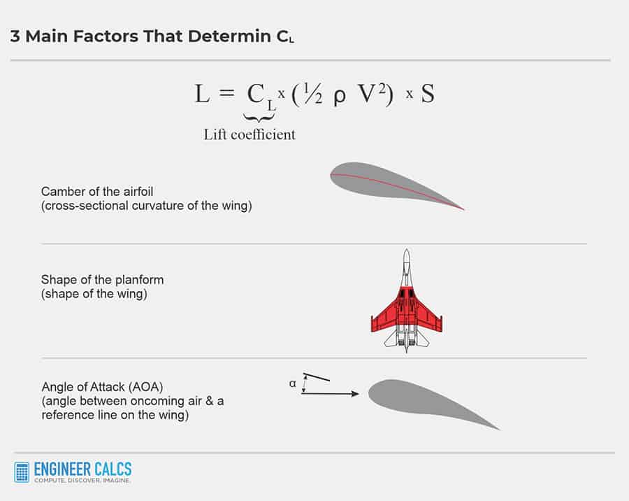
: The airplane manufacturer has most of the control over this dimensionless figure, which is influenced by:
- Camber of the airfoil
- The shape of the planform
- The Angle of Attack (AOA)
Check out the graphic below to see these three factors.
Which lift coefficient factors can pilots control?
The only thing pilots can control is the AOA. It’s the angle between the oncoming air (or relative wind) and a reference line on the airplane. By adjusting the plane’s pitch, the pilot changes the AOA, which in turn affects lift.
But if the AOA changes with a certain speed adjustment, the lift might not change. Instead, the plane maintains level flight while only the lift coefficient changes.
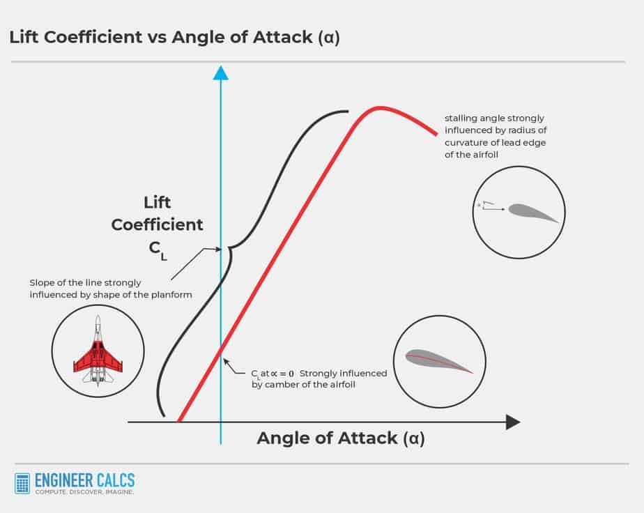
Lift Coefficient vs Angle of Attack
The relationship between the lift coefficient and AOA can be best visualized in the graph below.
To increase , you need to increase the AOA. But be careful – crank up the AOA too much and the airplane will stall, causing lift to drop. That’s when the graph starts to head downward.
Each airplane has a unique lift coefficient versus AOA graph, which depends on:
- The shape and size of the wings
- The curvature of the leading edge of the airfoil
What’s the takeaway with all these lift variables?
Most of the factors affecting an airplane’s lift are controlled by the manufacturer. There are many complex and interdependent variables at play during takeoff, as we’ve discussed.
For instance, if I increase the pitch of an airplane by 5°, it’s hard to tell how the AOA impacts lift. Maybe I also reduced my airspeed to maintain a constant altitude with the increased AOA.
Conclusion
The F-14 Tomcat will always be a pop culture icon, thanks to the Hollywood movie Top Gun. I remember dreaming of becoming a fighter pilot just because of that movie.
Years later, I discovered that the F-14 Tomcat had its share of shortcomings. For one, it was designed before computer-aided design assistance existed, which led to some aerodynamic flaws. But still, it was an incredible engineering achievement for its time, and it looks just as badass today. I’m amazed that such a heavy machine could take off from a mere 300-foot runway.
What do you find most fascinating about an F-14 Tomcat carrier launch? Which part of the engineering behind an F-14 Tomcat carrier launch do you think is most critical?
Featured Image Photo Credit: U.S. Navy via Photographer’s Mate 3rd Class Todd Frantom (image cropped)
Author Bio: Koosha started Engineer Calcs in 2019 to help people better understand the engineering and construction industry, and to discuss various science and engineering-related topics to make people think. He has been working in the engineering and tech industry in California for well over 15 years now and is a licensed professional electrical engineer, and also has various entrepreneurial pursuits.
Koosha has an extensive background in the design and specification of electrical systems with areas of expertise including power generation, transmission, distribution, instrumentation and controls, and water distribution and pumping as well as alternative energy (wind, solar, geothermal, and storage).
Koosha is most interested in engineering innovations, the cosmos, sports, fitness, and our history and future.