The per unit method short circuit calculations are the go-to method when solving power system problems by hand or checking software outputs.
I’m going to dive into the most important calculations for various power system scenarios, and you’ll learn how to apply the per unit method to these sources of short circuit currents:
- Electric utility systems
- Generators
- Synchronous motors
- Induction motors
But first, let’s chat about short circuit currents and the per unit method to understand why these calculations are so crucial.
Short circuit currents: The lowdown
As you’d expect, power engineers aim to design power systems that are both safe and reliable, and this includes protection from short circuits. If not accounted for, short circuits can lead to some nasty stuff, like:
- Power outages
- Interruption of essential facilities and services
- Equipment damage (imagine equipment turning into a fireball!)
- Injuries or even fatalities
- Facility fires
Obviously, we want to steer clear of short circuits. However, despite our best efforts, they still occur occasionally due to reasons like:
- Loose electrical connections
- Pesky rodents in equipment
- Voltage surges
- Insulation deterioration
- Moisture or dust accumulation on equipment
- Objects finding their way into electrical equipment (e.g., tools and tape)
When a short circuit happens in a power system, these things occur:
- The short circuit current flows from all connected power sources to the fault location.
- Arcing at the fault location can lead to fires and burning.
- System voltages drop relative to the short circuit current magnitude. At the fault location, the voltage can plummet to zero for a max fault.
- All equipment carrying short circuit current will experience thermal and mechanical stress, depending on the current magnitude and duration.
Basic per unit representations
Alright, let’s set up the typical per unit relationships for three-phase ( ) systems. We’ll kick things off with these base values:
- Base volts = line-to-line volts
- Base kVA = three-phase kVA
Now, let’s get down to the basic per unit relationships:
Per unit volts 
Per unit amps 
Per unit ohms 
Equally important, here are the derived base value equations:
Base amps 
Base ohms 
Lastly, to convert from percent (per) on an old base to per unit on a new base, do this:


Important Note: The per-unit system has four base values you need to know: base kVA, base volts, base ohms, and base amps. If you’ve got any two of these values, you can easily find the other two.
Most of the time, you’ll assign kVA and voltage as a study’s base values. Then, you can determine base ohms and amps for each voltage rating in the power system.
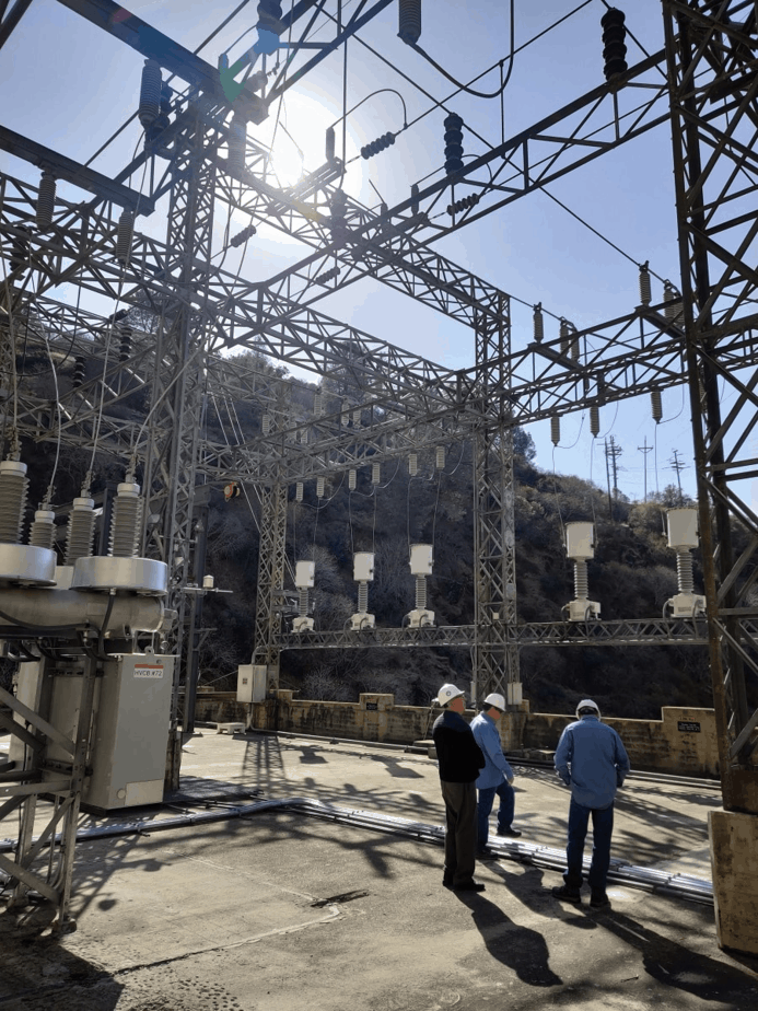
#1 Electric utility systems
Electric utilities supply short circuit current through their trusty system generators. They’re the heroes that power up our homes and businesses. But hold on, these generators don’t send electricity directly to customers.
Instead, utilities connect to us through transformers. Transformers are like the middlemen, adjusting voltage and current levels. They don’t create voltage or current themselves, though.
So, when a short circuit reaches a customer through a transformer, it’s influenced by:
- The transformer’s secondary voltage rating and impedance.
- The impedance of the generator(s).
- The impedance of the circuit from the generator(s) to the transformer’s primary terminals, and from the transformer’s secondary terminals to the fault location.
In Section #2, we’ll dive deeper into the world of generators.
Per unit method short circuit calculation
We’ll convert these five examples to per unit on a 100,000 kVA base.
Example #1: The available short circuit is 750,000 kVA or 750 MVA.

Example #2: The available short circuit is 35,500 amps at 12,470 volts.

Example #3: The equivalent utility reactance is 0.5 per unit on a 500,000 kVA base.

Example #4: The equivalent utility reactance is 0.55 ohms per phase at 12,470 volts.

Example #5: A 5,000 kVA transformer with an impedance of 7% on its kVA rating. Assume the impedance is all reactance.

#2 Generators
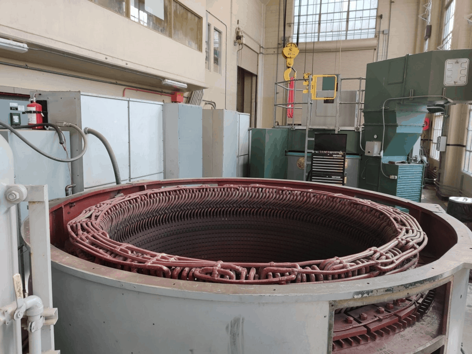
Prime movers drive generators. Some examples include:
- Turbines
- Diesel engines
- Gas turbine
- Water wheels
So what happens if there’s a short circuit in the circuit fed by the generator?
Well, the generator will keep on producing voltage since its DC field excitation is still maintained. Plus, the prime mover will keep pushing the generator at a normal speed.
Imagine a hydroelectric facility: water from the reservoir keeps flowing and turning the turbine, which then powers the generator. As a result, the generator voltage generates a short circuit current that flows from the generator to the fault location. The current is limited by:
- Generator impedance
- Impedance of the circuit between the generator and the fault location
And guess what? Short circuits can even happen right at a generator’s terminals! In this case, the generator’s impedance is the only thing limiting the output current.
For a short circuit calculation using the generator per unit method, see the next section. It’s worth noting that the calculations for generators and synchronous motors are quite similar.
Important Note: Synchronous generators and synchronous motors are like two peas in a pod – they’re both synchronous machines. The synchronous generator transforms mechanical energy into electrical energy, while the synchronous motor does the opposite.
#3 Synchronous motors
Now, let’s chat about synchronous motors. As we’ve learned, they’re a lot like generators, and their construction is nearly identical.
In a synchronous generator, there’s a stator winding where alternating current flows, creating a rotating magnetic field. But there’s also a field excited by direct current.
This direct current generates torque through a second magnetic field, allowing the rotor to synchronize with the speed of the stator’s rotating magnetic field. In a way, this other magnetic field is more stationary relative to the main rotating magnetic field.
Under normal circumstances, a synchronous motor operates by drawing AC power from its connected line and converting electrical energy to mechanical energy. But when a short circuit occurs, the system voltage drops significantly, causing the motor to stop delivering energy to the connected mechanical load. As a result, the motor slows down.
However, the inertia of the motor rotor and load will continue to drive the synchronous motor – just like how the prime mover keeps driving the generator in a hydroelectric facility. In this situation, the synchronous motor acts as a generator, delivering short circuit current for several cycles after the short circuit occurs.
Important Note: A motor can transform into a synchronous generator when it’s run by an external prime mover. This can happen if the three-phase power supply is cut off while the DC field supply remains. In our case, the inertia after power shutoff keeps spinning the “motor.”
The amount of short circuit produced depends on:
- Synchronous motor impedance
- Impedance of the circuit between the motor and the fault location
Per unit method short circuit calculation
We’ll convert the following example to per unit on a 100,000 kVA base.
Example: A 1,000 HP, 0.8 pf, synchronous motor has a subtransient reactance ( ) of 20%.
Motor kVA = 0.746 x 1,000/0.80 = 932.5 kVA

#4 Induction motors
Just like their synchronous counterparts, induction motors have a similar behavior when a short circuit happens. Picture this: the motor’s rotor and load keep spinning with their inertia, even after a short circuit takes place.
But here’s the catch. Induction motors don’t rely on a supporting DC field winding. However, a magnetic flux is present when they’re up and running. This flux is generated by induction through the stator, not a DC winding, and acts just like the DC field winding of a synchronous motor. As long as there’s voltage from an external power source, the motor rotor flux stays normal.
Now imagine a short circuit occurs, and the external voltage source vanishes. But the motor rotor’s flux can’t change in a snap, can it? Nope! The inertia of the motor’s spinning parts keeps it going, which then generates voltage in the stator winding.
And there you have it! A short circuit current flows from the motor to the fault location, lasting a few cycles until the rotor flux fades to nothing. The amount of short circuit produced hinges on:
- Motor impedance
- Impedance of the circuit between the motor and the fault location
Per unit method short circuit calculation
We’ll convert to ohms per phase at 4,160 volts.
Example: A 4160-volt motor control center has a connected motor load of 2,000 HP at 0.8 pf. The motors boast a reactance of 20% on a kVA rating of 2,000.
Motor kVA = 0.746 x 2,000/0.80 = 1,865 kVA
 ohms per phase at 4160 volts
Conclusion
Mastering per unit method short circuit calculations is a must for power engineers. It helps you understand short circuit calculations and power systems in general. Plus, it’s essential for sizing a current limiting reactor for a substation.
Just make sure you’ve got a solid grasp on the basics and all the sources of short circuit currents. Otherwise, you might make sneaky little mistakes that are hard to catch.
What do you think about per unit method short circuit calculations? What’s the most common source of short circuits you come across?
Hello! Thank you for this article! I found it helpful. I do have a couple questions, though:
1. In examples #6 and #7, it appears that the HP rating was used in place of Motor kVA. Can you please clarify? Shouldn’t this have been converted to kVA first?
2. In the second “Important Note” I think the energy types are switched. “The synchronous generator converts electric energy to mechanical energy. While the synchronous motor converts mechanical energy to electric energy.” This does not agree with what the article says later about synchronous motors.
Hi Krista,
Great eye!
1) Yes, it should have been – I made the revision. Generally, what I had originally written is more conservative; thus, why you’ll typically come across this calculation without the conversion.
2) You’re absolutely right. Typo on my end. Thanks for the catch!
Date: 12-JANUARY-2023 (Thursday)
Here’s greetings of a MERRY CHRISTMAS and a happy New Year 2023 to all !, Indeed, the PER UNIT Method of calculating or solving short circuit current fault at any point in the electrical power system circuit is realy powerful and relatively simple to apply and one which I have learned to use in my old company and one which is common to Western countries. However, there is another method which is bein gused in the Middle East countries which is based in the IEC-60909 std. and originated and implemnted in Eurpope, which is basically employing Impedance Method referring from Thevenin’s Theorem. But this latter is more complicated to use since there are factors which must be considered before actually finding the various S.C. faults type and values and applying voltage factor c. But for me, I think the PER UNIT Method is more practical and easy and easy to check back the S.C. fault resulting value by changing the KVAbase reference with another value to check back the answers. T.Y. !, by FMSJR.