Batteries are the lifeline to substations, providing backup power. I’m going to go over a typical substation battery sizing calculation.
We’ll take it step by step, highlighting the key factors you need to consider for various substation loads. But first, let’s take a moment to appreciate the vital role these batteries play in keeping our world electrified.
The lifeline of substations is batteries
Substations are the heart of the power grid, transforming voltage levels and ensuring we have electricity to light up our homes and charge our devices. Without them, we’d be left in the dark. That’s why substations rely on batteries to guarantee their essential operations can function around the clock.
You might be wondering why substations even need batteries. The answer lies in the unreliability of the primary AC power supply. If a transmission line or power source goes down, we could lose power entirely. That’s where our trusty batteries come in, providing much-needed backup power to keep everything running smoothly.
To get a better handle on the role of substation batteries, let’s take a gander at a schematic diagram.
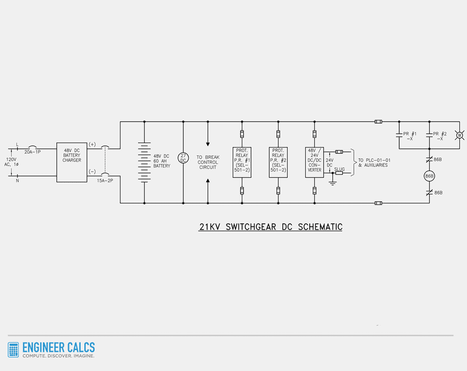
Notice how the 120V AC power supply feeds the 21kV switchgear protection loads. But these loads are all powered by 48V DC. To make this happen, we use a battery charger. This device converts the 120V AC supply to 48V DC while keeping the 48V DC battery charged and ready for action.
What’s float (trickle) charging?
It’s a way of keeping a battery charged by applying just enough continuous voltage and current to maintain a full or near-full charge.
Think of it as a battery’s standby mode. The battery is always fully charged, ready to become the backup power source if the AC power supply fails.
How does the battery system work?
The battery is always on standby, eager to power your system. When you’re hooked up to the AC power supply, two things happen:
- The battery charger trickle charges the battery as needed.
- The AC power supply powers the loads through the battery charger.
If you ever need a power boost or the AC power supply fails, the battery steps up without missing a beat. This is the beauty of having an independent power source like a battery in your system – no more stressing about power outages.
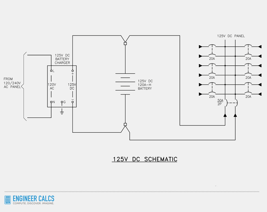
Low voltage power schematic with a DC panel
Now let’s take a peek at a low voltage power schematic with a DC panel. This schematic is similar to the previous one, but now the battery charger feeds a 125V DC panel that powers all the critical DC loads. Once again, a floating battery serves as a backup in case of AC power loss.
Checking out these schematics, it’s clear that batteries play a key role as a backup to the AC power supply. But their importance doesn’t end there – batteries also:
- Keep microprocessor relays, control circuits, emergency lighting, and communication equipment powered up.
- Ensure uninterrupted power when it’s needed the most.
- Activate power circuit breaker trip and close coils.
- Keep motor-operated air breaks, valves, pumps, and fans moving.
Without reliable DC backup power, substations and downstream equipment could suffer damage, and safety hazards may arise.
Substation battery sizing calculation
Now, let’s do some math and size a flooded cell, lead-acid battery for a substation. The battery will be rated 125V DC nominal and have an amp-hour capacity rated for an 8-hour rate of discharge.
In most substations, the 8-hour rate of discharge is the standard. It gives operators a solid 8-hour window to sort out any AC power supply issues before everything goes haywire.

Important Note: We’ll be using the IEEE Standard 485 for our substation battery sizing calculation. This standard helps us define DC loads and size lead-acid batteries.
But first, let’s quickly go over the two types of loads in a substation:
- Continuous loads usually run for 8-hour periods.
- Momentary loads only operate for less than a minute.
With that out of the way, let’s jump into the loads for our substation battery sizing calculation.
Continuous load list
- Auxiliary relays & timers: (10) x 5VA = 50VA
- Indicating lights (LED): (20) x 5.5VA = 110VA
- Multifunction relays: (18) x 5VA = 90VA
- Power meter: (16) x 10VA = 160VA
- SCADA allowance: 1000VA
Total: 50VA + 110VA + 90VA + 160VA + 1000VA = 1,410VA

Important Note: “Multifunction relays” include all your regular protection relays like 86L, 86B, 86T, 151T/151N, 87A, 51AT, and so on. We’ll group them together to make things simpler in our calculation.
Each relay usually has a load no greater than 5VA, but make sure to double-check each relay’s load individually.
Intermittent load list
- Auxiliary relays: (5) x 5VA = 25VA at 1 second
- Breaker close coil: (20) x 150VA = 3,000VA at 0.05 seconds
- Breaker spring winding motor: (20) x 500VA = 10,000VA at 5 seconds
- Lockout relays: (6) x 325VA = 1,950VA at 0.01 seconds
- Breaker trip coil: (20) x 150VA = 3,000VA at 0.03 seconds
Total summed design load
Peak load ( ) = Continuous load + Intermittent load


Important Note: Sometimes, both the ‘main breaker trip coil’ and ‘breaker close coil’ aren’t factored into the peak load calculation. Take, for instance, a generator breaker at a hydroelectric facility. When a trip occurs, it usually hints at a more significant problem requiring further investigation by an operator before closing the breaker.
In a hydro facility, backfeeding into the power system can be risky business, so we need to tread carefully. As a result, a situation where a breaker trips and closes immediately just doesn’t happen too often. To prevent overestimating the load, we include only the trip or close coil in our calculations.
Design load  , where:
 = contingency for future load growth (assume 10% = 0.1)
 = design contingency margin (assume 10% = 0.1)


Design energy demand calculation
 , where:
- = contingency for future load growth (assume 10% = 0.1)
- = design contingency margin (assume 10% = 0.1)


= 11,293.97VAh
= 11,293.97VAh (1+.1)(1+.1)
= 13,665.70VAh
 = Minimum battery capacity in Ah
 , where:
 = design energy demand (VAh)
 = nominal battery bank voltage (Vdc)
 = battery ageing factor (%). This value captures a battery’s decrease in performance due to age.
 = temperature correction factor (%). This value captures the ambient installation temperature. Use the temperature correction factor table from IEEE-485.
- = capacity rating factor (%). This value captures the voltage depressions from battery discharge.
 = system efficiency (%). Allowance for losses in the battery.
 = maximum depth of discharge (%).
Below, we’ll assign values to our above-listed variables:
- = 13,665.70VAh
- = 125VDC
- = 1.25 aging factor
- = 1.19 (50°F ambient)
- = 1.1
- = 0.97
- = 0.8 (80%)

Next, we increase the calculated battery capacity by 125%. This ensures the battery meets our design requirements throughout its entire life.
125% of 138.81 Ah = 173.51Ah
Important Note: It’s crucial to pick a battery amp-hour capacity that’s bigger than the minimum calculated capacity. Plus, be sure to specify the battery discharge rate, aka the C rating. For instance, if you want your battery to discharge for 24 hours, use C24 in your battery call-out.
Our battery will have a minimum rating of 200Ah at an 8-hour rate, or C8.
Sizing the substation battery charger
Required charger rating:  , where:
- A = required charger output rating
- k = efficiency factor (1.1 for lead acid batteries)
- C = calculated Ah discharge from the battery based on the duty cycle
- H = recharge time (8 hours)
 = continuous load in amps
 Amps
Amps
125% x 30.37 amps = 37.96 Amps. So, the battery charger will have a minimum output rating of 40 amps.
Important Note: All batteries have internal resistance, which causes the cell voltage to decrease as it depletes. The 125% multiplier accounts for this voltage drop to ensure the battery is not undersized.
Important battery notes
1) Heavy discharge: Lead-acid batteries prefer intermittent loads over continuous loads. Intermittent loads give batteries a rest period to recompose their chemical reaction.
2) Battery room ventilation: Lead-acid batteries release hydrogen gas when recharging. Without proper ventilation, hydrogen gas builds up and increases explosion risks.
3) Battery room temperature: The optimum temperature for lead-acid batteries is normally between 68-77° Fahrenheit. If the temperature goes too much higher, battery life will shorten.
4) Slow charging: Lead-acid batteries charge slowly. The typical charging time is 14 to 16 hours.
5) Full state of charge: Lead-acid batteries need to always remain fully charged. A low charge causes sulfation, leading to attenuated performance.
6) Charging voltage: To maintain optimal battery performance, it’s important to use the correct charging voltage limits. A low voltage limit can cause poor battery performance and sulfation buildup on the negative battery plate. On the other hand, a high voltage limit can improve performance, but it can also cause grid corrosion to form on the positive battery plate.
It’s super important that your battery charger applies the appropriate voltage to a fully charged battery. This way, you’ll avoid overcharging and any potential damage.
Substation battery sizing calculation wrap up
Sizing your substation’s batteries doesn’t have to be a headache. Just gather your load info (okay, that part might be a bit tedious) and you’re all set.
Think of a power substation like a massive machine. Like any machine, it needs backup plans for its critical components. Redundancy is key! So, make sure to include the right-sized batteries and chargers in your substation setup to avoid costly downtimes.
Do you have any substation battery sizing tips? Where else have you seen batteries providing backup to the main power source?
clear explanation with example
Glad you found it helpful.
I am finding some basic arithmetic errors here
for example in total summed design load the author took
1410 + (25 +3000 +1950 +10000) where that should be 1410+25+3000+3000+1950+10000
because although you don’t trip and close at the same time, they both contribute to the energy storage load, unless you plan to trip and never close.
the energy demand paragraph the author takes 1410VA*8h + [25VA by 1minute *1hour/60minutes] where 25VA was listed as a 1 second momentary load not 1 minute and therefore calculates 25VA load for 1 minute; should be 25VA/3600seconds
Great observations!
#1) Upon reviewing the calculation, I realized that it was based on a hydroelectric facility, even though the article is about substations. I’ve revised the calculation and added a note to explain that it’s common practice for generator breakers at hydroelectric facilities not to be instantly closed after a trip incident.
#2) The design energy demand calculation used 1-minute figures to generate more conservative values. To avoid confusion, I’ve revised the calculation accordingly.
This came at the right time for me, Great content. Thank You for a detailed and precise way of addressing this topic.
Hello Sir, I find your article very useful and relevant to my work as a maintenance personnel in a distribution Utilities. I have a query sir. 1) In our 20 MVA Substation, we are going to replace our 48 VDC Batteries (4-12 VDC batteries, 100AH into 2Volts, 200AH batteries (24pcs.). This is to have a longer years for the batteries to operate. My question is: a) Is there a need to upgrade the charger since we will upgrade the battery’s AH? the charger is rated at 25A, 48V output, and 240V input. The continuous load is at 3.8 A. thank you.
Glad you found it helpful!
As an off-the-cuff reply, you probably would need to replace the charger, but there are other variables you need to consider too. Thus, you need your engineer on record to review the existing charger’s compatibility.
I found it very helpful
Glad you found it to be helpful.
Batteries with step loads as you have described will inherently decrease in voltage as they progress further into their 8 hours cycle. While you might float the batteries at 130VDC you typically have an end voltage of somewhere around 105VDC. Your calculations utilize the nominal voltage of 125VDC but battery load profiles will show you that the battery voltage will continuously taper off during the load draw. IEEE recommends you use the lowest voltage of your battery to calculate all your loads and during sizing. Additionally if you use any large battery manufacturer sizing programs, you will find that they as well utilize the end voltage to convert VA(W) to Amps. While I agree using the end voltage is ultra conservative, the method of using the nominal voltage is incorrect and results in undersized batteries for true use. You have masked that by adding all of your % increases but ultimately it will not be sized sufficiently for the full life cycle.
Michael, thanks for your great comment.
Yes, all batteries have an internal resistance, and the cell voltage decreases as it depletes.
The 125% you’re referencing, accounts for the slack with the voltage drop. This percent actually outputs a more conservative value than using 105V. While noting, 105V is another assumption value similar to the 125%. Using the nominal value with a thought-out multiplier is more practical than thinking you have precision with the 105V value.
To also point out, the VAs are not constant, as each device is based on a range of voltages. While noting, as the voltage drops on a DC system, the current drops as well (assuming a constant resistance). This needs to be considered as well.
Your comment highlights how the post needs some added clarity with the percentage though. I added a note.
Hello,
Thank you for this very informative article. I was wondering if the 8 hour rate of discharge is discussed in IEEE standards as a typical rate to use in substations or this is just an industry practice?
Also, are there any regulatory requirements (i.e. NERC, FERC, etc.) that mentions how long the rate of discharge should be?
Generally speaking, with substations you want a short duration high discharge battery. Also, you want to ensure the battery has the capacity to support the load and trip per IEEE 450 (e.g. maintaining a minimum battery voltage).
Hi Josh,
It’s an industry standard, but you’ll come across various requirements from customer to customer. There are recommended battery sizing practices in IEEE 485 as well.
In short, you want ample backup power allowance for operators to restore AC power or make any necessary control decisions.
Short and useful