Choosing the right mechanical design tolerances keeps projects within budget and, more importantly, ensures designs stay functional.
Now, I’m no mechanical engineer or machinist, but as an electrical engineer, I’ve tinkered with devices both at home and at work, so I know a thing or two about tolerances.
At first, I was completely baffled by mechanical design tolerances. I’d fiddle with a design, clueless about what a reasonable tolerance should be. My friends’ advice didn’t help either. They’d throw out a number without explaining why or tell me to write “critical dimension” and let the factory figure it out. That’s a recipe for disaster.
Instead, I needed answers to these questions:
- What tolerances are realistically achievable?
- How repeatable can a given tolerance be in a design?
- What’s the cost for varying tolerances?
- How do tolerances vary when using different materials and machines?
So, buckle up, ’cause I’m diving into these questions and dishing out 8 tips. I know from experience how frustrating it can be to choose design tolerances. But first, let’s break down what tolerances are all about.
What is dimensional tolerancing?
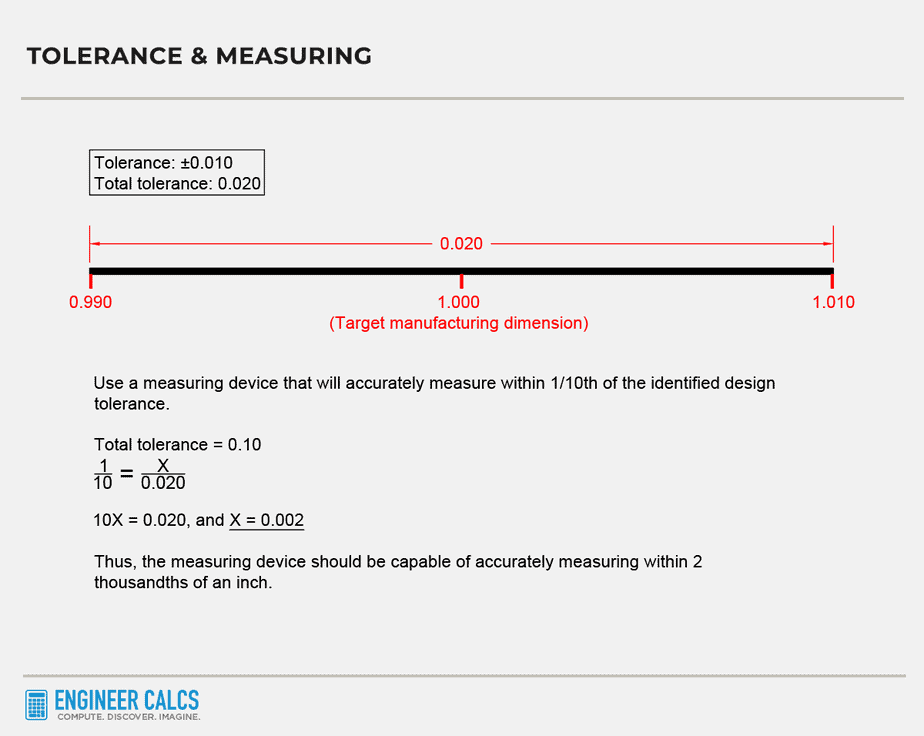
Well, it’s all about how much wiggle room you can allow in a measurement while still having your design work perfectly. Picture this: you need a metal piece cut to 64 inches. You don’t just tell the factory, “Hey, cut a 64-inch piece, will ya?” That’s because you’ll never get an exact 64-inch piece – it might be 64.1 inches or even 63.9 inches. Instead, you give them a little leeway, like a +/- 0.1-inch tolerance. That way, the machinist knows the piece can be between 63.9 and 64.1 inches, giving you a max and min limit for quality control.
To really hammer home the concept of tolerances, check out this example:
Now, you might think that tighter tolerances mean better designs, right? Well, yes and no. Tight tolerances can lead to better-fitting parts and sleeker designs, but they also bump up the cost and time it takes to make them. This is because factories need pricier, more precise machinery and skilled workers to get the job done.
Ever bought a cheap piece of furniture and found the screw holes don’t line up? That’s a prime example of poor tolerances. Your excitement quickly turns to frustration, and you learn the hard way – you get what you pay for.
#1 Understanding the costs associated with tolerance selections
First, figure out how precise your tolerances need to be for your design to work. The best designers can maintain functionality with the loosest tolerances – that’s the art of design.
The table below, from the Machinability and Machining of Metals, shows the increase in cost with tighter tolerances:
| Surface finish technique | Tolerance | Approximate relative cost |
|---|---|---|
| Rough machining | +/- 0.030 | $101 |
| Standard machining | +/- 0.005 | $200 |
| Fine machining | +/- 0.001 | $440 |
| Very fine machining | +/- 0.0005 | $720 |
| Fine grinding | +/- 0.0002 | $1,400 |
| Very fine grinding | +/- 0.0001 | $2,400 |
| Lapping, polishing | +/- 0.00005 | $4,500 |
Now imagine applying these tight tolerances to multiple dimensions of your product. The expenses stack up rapidly, especially when producing thousands of units. These higher costs come from:
- Expensive tools
- Highly paid expert machinists
- Advanced processes for machines and tools
- Detailed inspections to verify tolerance quality
To dodge soaring costs, be certain you genuinely need those tight tolerances. I always suggest beginning with the loosest tolerances possible and only tightening them as required.
Moreover, familiarize yourself with various parts and products to make sound judgment calls. For instance, computer hardware will require tighter tolerances than furniture.
Get to know tolerance standards to better visualize the necessary tolerances. You’ll discover numerous tolerances already in use across the engineering world. By doing so, you can pinpoint suitable tolerances and save both money and time, as shown below.
#2 Keep an Eye on Measurement Instrument Errors
No measuring tool is perfect, and there’s always some error tied to a tool’s position in dimensioning. To complicate matters, this positioning error grows as measurement distances increase.
Check out the table below to see how positioning errors increase from point A to G:
| Segment parts of a single product | Target measurement | Actual measurement |
|---|---|---|
| A to B | 10 inches | 10.5 inches |
| B to C | 10 inches | 10.3 inches |
| C to D | 10 inches | 10.4 inches |
| D to E | 10 inches | 10.6 inches |
| E to F | 10 inches | 10.2 inches |
| F to G | 10 inches | 10.5 inches |
The total target measurement from A to G is 60 inches, but the actual total measurement is 62.5 inches. Now, picture needing to align a hole at part G with another identical part measuring 60 inches. You’d be off by another 2.5 inches. So, be crystal clear about your tolerance expectations with manufacturers.
#3 Striking the Balance Between Tight Tolerances and Common Sense
If you set your tolerances too tight, you’re bound to face issues. I once saw an engineer designate a +0.05/-0.00 tolerance for a 2.00-inch hole and a +0.00/-0.005 tolerance for the corresponding 2.00-inch shaft.
If the machinist sticks to the median of these tolerances, the shaft will rotate freely within the hole. But what if the machinist cuts both the hole and shaft to exactly 2.00 inches? You’ll have 0.00-inch clearance, and the shaft won’t budge.
And guess what? It’s not the machinist’s fault – they stuck to your design tolerances. So always plan for the worst-case scenario in your designs, ensuring enough clearance for everything to work smoothly.
It’s smart to use established tolerance guides, but keep in mind that some can be crazy precise. These tables often rely on stats and theory, sidelining practical manufacturing methods.
No worries, though! As an engineer, you can point to a standard table while guiding the machinist toward the best manufacturing method to achieve your goal.

Important Note: For large dimensions, pinpoint accuracy isn’t always needed. For instance, a 20-foot beam doesn’t need to be cut to four decimal places. Make it clear to the machinist what you really want, or they might waste time trying to cut the beam to 20.0000 feet, which is just plain silly.
#4 Real-world factors impacting tolerances
There are a ton of real-world factors that can impact your tolerance choices, so make sure you’ve got your ducks in a row before diving into the design work. Trust me, doing this will save you from a world of future headaches. When I’m deciding on tolerances, I always take into account things like:
- Bearing load
- Surrounding humidity and temperature
- Length of engagement
- Lubrication amount
- Material type
- Association with movement and speed
Material choice is super important too, as a material’s physical and mechanical properties can make or break your tolerance levels. For example, some materials might get too brittle if cut too thin.
And let’s not forget about extreme temperatures! Thanks to thermal expansion, materials generally expand when heated and contract when cooled. So, take a step back and look at the big picture before locking in your tolerances. Don’t worry, with experience, this process gets easier over time.
Important Note: The machinist who makes your part will work off your design, so don’t expect them to know everything about your material, like how it behaves in heat treatment—especially when you’re only paying them to cut for you. To avoid any confusion, your drawing should list all requirements for manufacturing your part, including the manufacturing process. Keep in mind, if you need your manufacturer to fill in the gaps in your design, your costs can skyrocket as the machinist needs to do extra research on your behalf.
#5 Verification of CAD settings and standards
Always make sure the tolerances set in your CAD software align with what you want. For instance, your CAD software might be set to use 4 decimal places instead of 1 for all your dimensions, which could result in tighter tolerances than necessary and send your project costs through the roof.
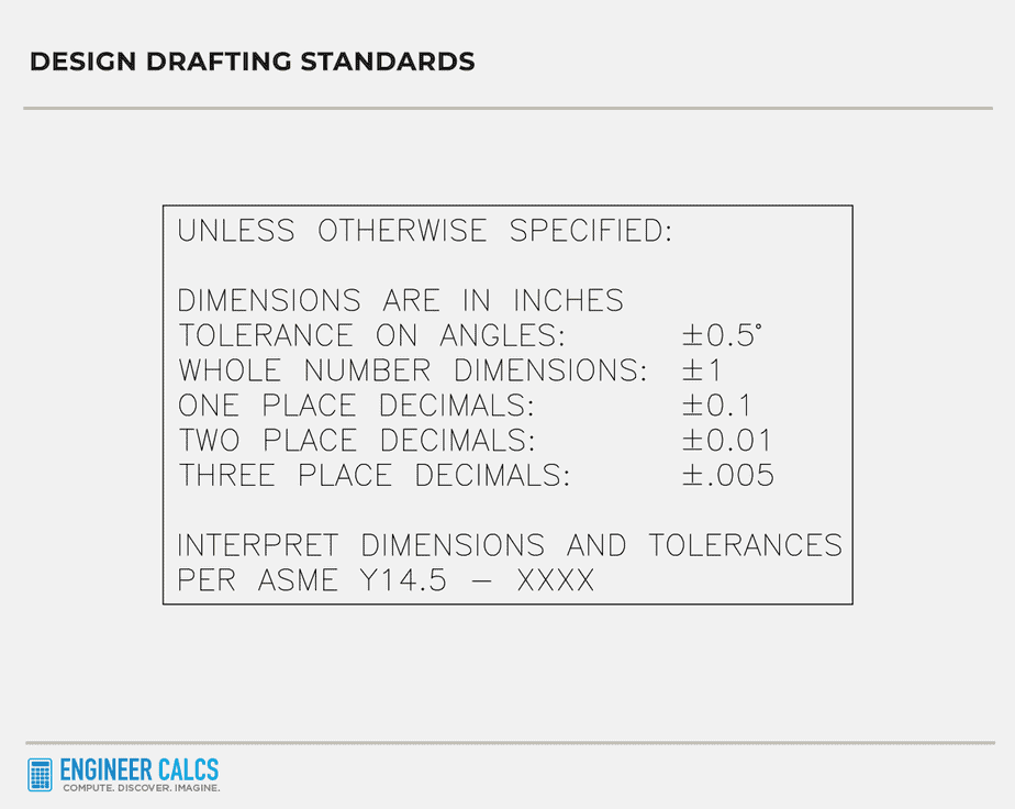
Also, check your design drafting standards in your title block. Make sure your drawings have your standards listed, as these are the default tolerances applied to dimensions when explicit tolerances aren’t listed. This acts as a legend for your machinist to follow. Plus, ensure that your listed standards match the specs of your project.
Just as important, use ordinate dimension sets in your drawings to specify a zero location in the X and Y-axis for each view of a part.
Important Note: You don’t always need to list out your dimensions. If you know a machinist and the project isn’t super precision-driven, you can keep things simple. For example, point to a hole with a leader reading “press-fit dowel,” and the machinist will know how to best ream it for a snug fit.
#6 Navigating the pitfalls of limit dimensions
Limit dimensions are a set of min and max values, with any value in between being acceptable. One common issue I run into with limit dimensions is that production personnel often machine parts consistently to the higher boundary. I get it; it saves time, reduces tool wear and tear, and acts as a safety net in case anything goes wrong. Since they like to stay on the safe side of tolerances, they’ll still have material left to rework if a piece is incorrectly cut.
The point is, be aware this happens. If you’re cool with it, no problem. If not, use bilateral tolerances, which provide a variation from your target dimension in both positive and negative directions (e.g., ±0.1 from the target dimension). This way, the machinist is more likely to cut at your target dimension.
Important Note: Limit dimensions helps eliminate ambiguity. Sometimes, machinists may become confused with unilateral tolerances. For instance, imagine that you have specified a 6-inch shaft with a +0.05/+0.10 tolerance. In your mind, you expect the machinist to produce a shaft with a size ranging between 6.05 to 6.1-inches. However, I have received incorrect parts before because the machinist interpreted the tolerance as +0.05/-0.10.
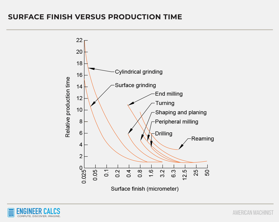
#7 Know Your Manufacturing Limits
When designing, you can dream up any tolerance your heart desires. But can your workshop actually deliver? Different manufacturing processes can handle different tolerances.
This is the classic struggle for us design engineers. So, always chat with your machine shop about what tolerances they can hit without breaking the bank. Work with the resources you’ve got! For instance, if your factory can only handle +/- 0.00X tolerances, but your design calls for +/- 0.000X, you’ll either need to outsource or risk low yield rates.
Also, always work out your tolerances first. They’ll dictate the manufacturing process you choose, not the other way around. And of course, your budget plays a big role in your decision.
Important Note: A manufacturing process isn’t set in stone. Achievable tolerances vary between workshops, depending on the machinist’s experience. At the same time, don’t go overboard specifying manufacturing processes. A good machine shop will help you pick the best method based on their tools and your project.
#8 Watch out for tolerance accumulation (stack up)
The tolerance between two points in your design hinges on the controlling dimensions. Knowing the max variation between those points is crucial because too much can throw your whole design off.
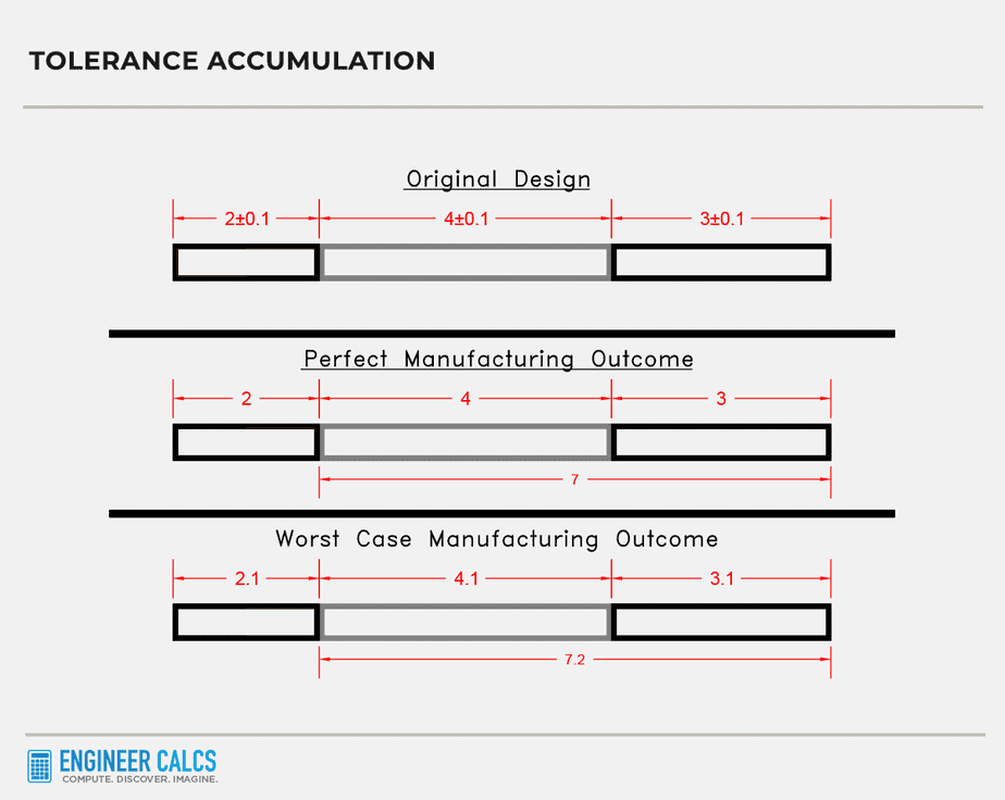
For example, check out the design graphic below that shows the best and worst-case scenarios. As the number of controlling dimensions increases, so does your tolerance stack-up. Your variance equals the sum of the tolerances from the controlling dimensions.
Important Note: Some dimensions might not list tolerances, but there’s always an implied tolerance.
Relative dimensions with mechanical design tolerances
When it comes to mechanical design tolerances, each tolerance in the path to the final dimension adds to the total system tolerance. Say you’ve got six back-to-back dimensions, each with a +/- 0.01-inch tolerance. The worst-case for the sixth dimension is the sum of all those tolerances, which is 0.6 inches above the target dimension.
That’s not ideal since your design might not work. So, if you want that sixth dimension to be +/- 0.01 inches relative to the first point, you’ll need to specify a new relationship. Provide a fresh dimension and tolerance, and leave out the middle tolerances.
Important Note: You need a solid grasp of your end design, understanding how all the parts fit together. Also, do tolerance stack-up analysis throughout your design work. That way, you won’t end up with a bunch of non-mating parts.
Conclusion
Mastering mechanical design tolerances is an art, and it’s a crucial part of many design projects. So familiarize yourself with tolerances, to avoid future headaches and costs. I recommend using specialized software to help you analyze mechanical design tolerances. The software can flag potential tolerance stack-up issues and more.
But above all, use your common sense. Figure out how parts will fit and function together. Then, design with the largest tolerances possible without sacrificing function. This will make you a better designer, and you’ll win over plenty of machinist pals.
What’s your biggest challenge when selecting mechanical design tolerances? Any tips or tricks to share when it comes to mechanical design tolerances?