The current limiting reactor sizing calculation is simple, but it’s also crucial for protecting certain power systems.
I’ll help you wrap your head around the essentials as we work through an example calculation for a 115,000V substation.
Before diving in, remember two things:
- I might just call current limiting reactors “reactors” from time to time.
- Each phase of our circuit needs a reactor. So, the reactor size we calculate will apply to each phase of our 3-phase AC power system.

Important Note: Electric circuits are like highways, with a starting point (the source) and a destination (the load), and electrons flowing like cars on a road. Just as a car accident can cause a traffic jam, a short circuit can mess up your electrical system.
That’s where reactors come in – they reduce short-circuit currents and protect your equipment.
What is a current limiting reactor?
These nifty devices transform electrical energy into magnetic energy. In simple terms, they’re big coils of wire that generate a magnetic field when electric current flows through them. As the magnetic field grows, it stores energy and eventually stabilizes.
The current flowing through the reactor is proportional to the magnetic flux it creates.
But the cool part is that the magnetic field created by the reactor fights against the flow of current, producing a back EMF or counter Electromotive Force (induced voltage opposing the applied voltage). It might sound bad, but it’s actually what helps limit short-circuit currents.
Instead of picturing voltage sources fighting each other, think of them balancing each other out. The reactor doesn’t wipe out the current; it just keeps it at a safe level.
The wire size and coil turns in the reactor are crucial for finding that balance. The wire needs to handle the full current while minimizing power losses.
So, even though reactors seem like a simple gadget, they play a vital role in keeping your electrical system safe and reliable.
Understanding equations related to current limiting reactors
First, let’s check out Impedance (Z), defined as Z = R + jX, where:
- R is resistance
- X is reactance, specifically inductive reactance in our case
When current (I) flows through an impedance, there’s a voltage drop of V = IZ. Plus, we need to think about these effects on power:
- Watt losses of:

- Var “losses” of

Important Note: Var losses aren’t the same as watt losses. Watt losses are energy lost as heat, but vars don’t vanish – they’re actually used by the reactor!
I’m calling them “losses” here to help balance the reactive power, kind of like how we balance real power with real losses.
Now, let’s talk about getting the most from our reactor. We want a reactor with low resistance to keep watt losses down, allowing electrical energy to become magnetic energy without losing power to heat. But, the inductive reactance needs to be high enough to limit short-circuit current flow.
The reactance rating directly impacts the magnetic field energy density. The higher the energy density, the more back emf is produced.
We see this in the equation. Var losses increase with the square of the current flow. So, when the current surges due to a short circuit, the magnetic field strengthens, creating a larger back emf, as represented by  . That’s why the reactor can’t eliminate the current. Without a change in current over time, we wouldn’t have a back emf.
In a nutshell, we choose the reactor’s inductive reactance to be low enough for an acceptable voltage drop during normal operation but high enough to limit the short circuit current through the created back emf. It’s all about striking the right balance between inductive reactance and resistance, like finding the perfect mix of ingredients for a recipe.
When to use a current limiting reactor?
If the short circuit current in your power system exceeds the interrupting rating of your electrical equipment, you could run into serious problems. This equipment includes:
- Switchboards
- Switchgear
- Motor control centers
- Circuit breakers
- Fuses
Each piece of equipment is designed to handle a max short circuit, known as its interrupting rating. It’s essential to ensure your equipment’s interrupting rating is greater than the max calculated short circuit before buying any gear!
The calculated short circuit value depends on your power source, which could be:
- Utility power
- Generator
- Renewable energy like solar PV systems that back feed into the power grid
Important Note: Short circuit currents in your power system are a moving target. They vary at every point and depend on factors like voltage and impedance.
When you sign up for new electric service, your utility company provides the available short-circuit current, usually at the terminals of the utility transformer feeding your facility.
This value shrinks as the current flows from the utility transformer downstream to your electrical equipment. Why, you ask? Well, it’s all because of the impedance of the conductors connecting the transformer to your gear.
What causes the short circuit current to increase?
Picture these scenarios:
Your power needs balloon, you bring in new power sources, and your utility source grows. All these changes shake up the short-circuit current in your system. For instance, if your utility keeps adding more substations each year, your system’s short circuit current might grow too.
Imagine your utility’s substation capacity doubles, soaring from 25,000 MVA to 50,000 MVA. As a result, the short circuit currents in the power grid go up, but your existing electrical equipment still has the same old interrupting ratings. These ratings are fixed values set by the factory that built your equipment.
That puts you in a tricky situation!
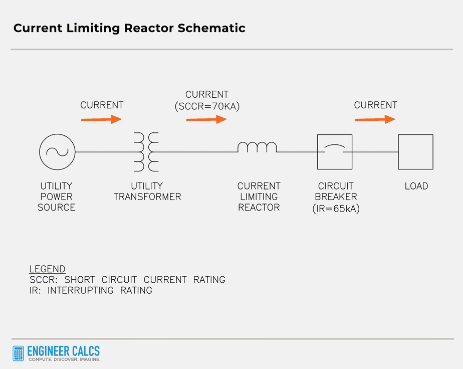
Current limiting reactor schematic
Below is a super basic one-line diagram, showing the short circuit current flowing from the utility power source to the load, with a current limiting reactor in between.
Now, the circuit breaker interrupting rating is 65,000 amps, but the short circuit current rating is 70,000 amps. Houston, we have a problem!
But don’t worry, we don’t need to replace all our existing electrical equipment willy-nilly. Instead, we can just install a current limiting reactor to bring the short circuit current down below 65,000 amps. Phew, crisis averted!
Important Note: Every piece of electrical equipment comes with an interrupting rating, which represents the highest current it can safely interrupt at a given voltage.
Imagine you’ve got a piece of equipment rated for 480 volts and an interrupting capacity of 65,000 amps. That means it can safely handle any short circuit below 65,000 amps.
Now, it’s absolutely vital that every piece of equipment in your power system can withstand the maximum available short circuit rating. Not only is this a best practice, but ignoring it could lead to code violations and seriously hurt someone, or even worse, cause a fatality.
Current limiting reactor sizing calculation
Alright, let’s dive into our current limiting reactor sizing calculation for our substation.
Let’s say the power transformer rating is: 24/32/40 MVA (OA/FA/FA)
The transformer has these voltage ratings:
- Primary voltage: 115,000 volts
- Secondary voltage: 12,470 volts
For our calculation, we’ll use the largest transformer rating of 40 MVA.

Important Note: OA/FA/FA are liquid transformer cooling classes.
OA: self-cooling through natural ventilation
FA: forced air-cooling with the help of fans
FA: another set of fans for additional forced air-cooling
Now, I’m going to use the per-unit system for my calculation.
The system impedance to our station looks like this:


Now, let’s check out the existing station fault impedance at the 12.47kV rating and 24MVA base:


Current limiting reactors for transformers connected in parallel
In the land of large substations, transformers connected in parallel are a common sight. Why, you ask? To supply even greater capacity! In our case, we’ve got three transformers and their respective current limiting reactors designed in parallel to reach the ideal total fault impedance of 0.0755 pu  , taking into account the system impedance of 0.0060 pu .
Linking our transformer trio and their reactors in parallel gives us an impedance of 0.0755 pu – 0.0060 pu = 0.0695 pu .
Now, each transformer and its reactor will have an impedance of 3 x 0.0695 pu = 0.2085 pu .
Assuming we’re working with a maximum transformer design impedance of 10.5% (or 0.105 pu ) on a 24 MVA base, we can calculate the impedance of the current limiting reactor as  at 24 MVA.
To get this value on our 40 MVA base, we just multiply by the ratio of the two bases, resulting in an impedance of  = 0.1725 = 17.25% at 40 MVA.
Similarly, the equivalent impedance of the transformer at 40 MVA can be calculated as  = 0.175 = 17.5% at 40 MVA.
The current limiting reactor rating
The reactor rating needs to be  , Z = 17.5% on a 40 MVA base. Plus, it’ll need some sturdy bracing to stand up to the 20kA available fault current.
On the flip side, the transformer boasts a rating of 24/32/40 MVA (OA/FA/FA) with Z = 10.5% on a 24 MVA base.
Important Note: The Z value is crucial for a current limiting reactor and transformer. Higher impedance means less short circuit current. But don’t just throw money at a high-impedance reactor and transformer – it’s not only pricey, but it can also crank up your circuit’s reactance to undesirable levels.
Calculating the short circuit current without the current limiting reactors
Let’s see how the short circuit rating skyrockets over 20,000 Amps when we don’t have current limiting reactors to keep it in check.


It’s plain as day we need those current limiting reactors. But, let’s not forget they have some drawbacks too:
- They increase the circuit’s total reactance, causing a reactive voltage drop and a lagging power factor. As a result, the power system’s voltage regulation takes a hit.
- They need room to be installed safely and to keep clear of magnetic flux exposure.
- The magnetic field generated by the coil might cause currents in large objects nearby.
- The cost of purchasing and installing current limiting reactors.
The downsides vary based on the reactor types and where you install them in your power system.
For the best results, always install the reactors where they’ll be most effective to work their magic. It may sound like a no-brainer, but in practice, it’s not always easy to achieve.
Important Note: Current limiting reactors are fantastic at reducing short-circuit currents, but they’re not a one-size-fits-all solution. Before installing them, make sure you’re clued up on how they’ll affect your power system.
To get a clearer picture of their impact, it’s wise to carry out a short circuit and load flow study.
Current limiting reactor sizing calculation wrap up
I hope you’ve learned a thing or two about current limiting reactors and how short circuit currents can impact power systems.
Once you’ve got the info you need, sizing a current limiting reactor is a breeze. But remember, you’ll also have to do other calculations to weigh the pros and cons of installing them.
Like any engineering decision, don’t rush into installing reactors. Take your time and think about all the factors to make the best choice for your power system.
What’s your take on current limiting reactors? Have you used or seen them in action in your work? Ever done a current limiting reactor sizing calculation before?
Featured Image Photo Credit: publicpowerorg (image cropped)
Author Bio: Koosha started Engineer Calcs in 2019 to help people better understand the engineering and construction industry, and to discuss various science and engineering-related topics to make people think. He has been working in the engineering and tech industry in California for well over 15 years now and is a licensed professional electrical engineer, and also has various entrepreneurial pursuits.
Koosha has an extensive background in the design and specification of electrical systems with areas of expertise including power generation, transmission, distribution, instrumentation and controls, and water distribution and pumping as well as alternative energy (wind, solar, geothermal, and storage).
Koosha is most interested in engineering innovations, the cosmos, sports, fitness, and our history and future.